Magnetic proximity sensors are essential components in modern automation and safety systems. These devices detect the presence or absence of a magnetic field, typically from a permanent magnet or an electromagnet, without physical contact. Understanding their function is greatly enhanced by examining magnetic proximity sensor images, which reveal their diverse forms, internal structures, and real-world applications. This visual guide explores the key types and uses of these sensors through the lens of their imagery.
A primary category visible in many magnetic proximity sensor images is the reed switch sensor. Photographs often show a small glass or plastic capsule containing two thin, ferromagnetic reeds. These reeds are separated by a tiny gap and sealed in an inert gas atmosphere. When a magnet approaches, the reeds become magnetized, attract each other, and make contact, closing an electrical circuit. Images highlight their simplicity, compact size, and the hermetic sealing that protects the contacts from dust and corrosion. These sensors are commonly pictured in security systems for door and window monitoring, where a magnet is mounted on the moving part and the sensor on the frame.
In contrast, images of Hall Effect sensors depict a solid-state electronic device. These pictures usually show a small, black, three-terminal integrated circuit or a module. Cross-sectional diagrams are particularly valuable, illustrating how a semiconductor material generates a voltage difference (the Hall voltage) perpendicular to both the electric current flow and an applied magnetic field. This voltage is then processed by onboard electronics. High-resolution photos often reveal the robust, encapsulated design suitable for harsh environments. Common visual applications include speed sensing in automotive anti-lock braking systems (ABS), where a sensor images a toothed wheel on an axle, and current sensing in industrial equipment.
Another prominent type is the magnetoresistive sensor. Detailed technical images and diagrams demonstrate how the electrical resistance of certain materials changes in the presence of a magnetic field. These sensors are known for their high sensitivity and ability to detect both the strength and direction of a field. Photographs often show them in chip form or as part of complex assemblies for precise angular or positional measurement, such as in robotic arm joints or electronic compasses in mobile devices.
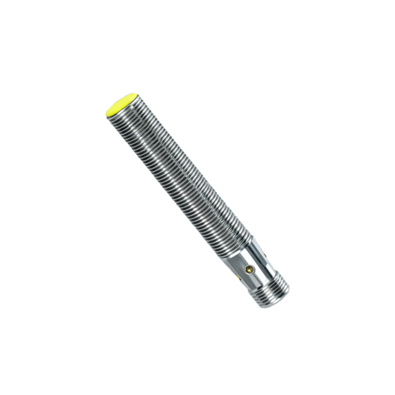
Industrial magnetic proximity sensor images frequently showcase rugged, cylindrical metal housings with threaded bodies, designed for easy mounting in machinery. These pictures emphasize features like LED status indicators, cable or connector types (e.g., M8, M12), and protection ratings like IP67, indicating resistance to dust and water immersion. Application photos are telling: a sensor might be shown detecting the position of a hydraulic cylinder on an injection molding machine, ensuring it stops at the correct point. In conveyor systems, images depict sensors counting metallic objects or verifying the position of pallets.
Automotive applications provide a rich source of illustrative images. Here, sensors are shown in challenging environments—covered in grime, subjected to extreme temperatures, and exposed to vibration. Pictures might detail a crankshaft position sensor mounted near the engine's flywheel, a critical component for engine timing. Others show gear tooth sensors or sensors used in electric power steering systems. The imagery underscores requirements for durability, reliability, and miniaturization.
When analyzing magnetic proximity sensor images for selection, several visual cues are critical. The sensing distance, a key specification, is often demonstrated in diagrams showing the gap between the sensor face and the target magnet. The type of output—digital (PNP/NPN) or analog—might be indicated by labeling or schematic symbols in the image. The operating principle, whether it's a unipolar sensor (triggered by a single south or north pole) or an omnipolar sensor (triggered by either pole), can sometimes be inferred from application setups.
In summary, magnetic proximity sensor images serve as an indispensable tool for engineers, technicians, and procurement specialists. They move beyond datasheet specifications to show physical form, scale, integration methods, and environmental suitability. From the simple reed switch in a home appliance to the sophisticated magnetoresistive chip in advanced robotics, these visuals tell the story of a technology that enables precise, reliable, and contactless detection across countless industries. By learning to interpret these images, one gains a practical understanding of how these silent, invisible magnetic fields are harnessed to create motion, ensure safety, and drive automation.