Introduction to 3-Wire Proximity Sensor Wiring
In industrial automation, 3-wire proximity sensors are fundamental components for detecting the presence or absence of objects without physical contact. These sensors typically operate on DC voltage and are classified as either PNP (sourcing) or NPN (sinking) types. The wiring configuration is crucial for proper integration into control systems, and color coding of the wires serves as a universal guide for electricians and engineers. Standardization in wire colors helps prevent installation errors, reduces downtime, and ensures safety. While variations exist based on manufacturer and region, a common color scheme has been widely adopted in the industry, distinguishing between power supply, output signal, and ground connections. Understanding this coding is essential for troubleshooting and maintaining efficient operations.
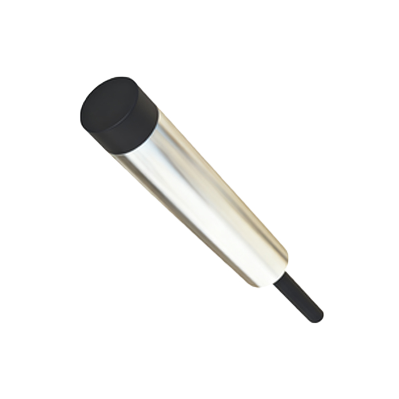
Standard Color Code Conventions
The most prevalent color standard for 3-wire DC proximity sensors involves three distinct wires: brown, blue, and black. The brown wire is universally designated for the positive DC supply voltage, typically ranging from 10 to 30 VDC. This wire connects to the positive terminal of the power source. The blue wire is consistently used for the ground or 0V connection, linking to the negative terminal. The black wire carries the output signal from the sensor. In a PNP sensor, the black wire outputs a positive voltage when an object is detected, while in an NPN sensor, it switches to ground or 0V upon detection. Some sensors may include additional wires, such as white for a complementary output or for configuration purposes, but brown, blue, and black form the core trio. Adherence to this scheme simplifies cross-manufacturer compatibility and training.
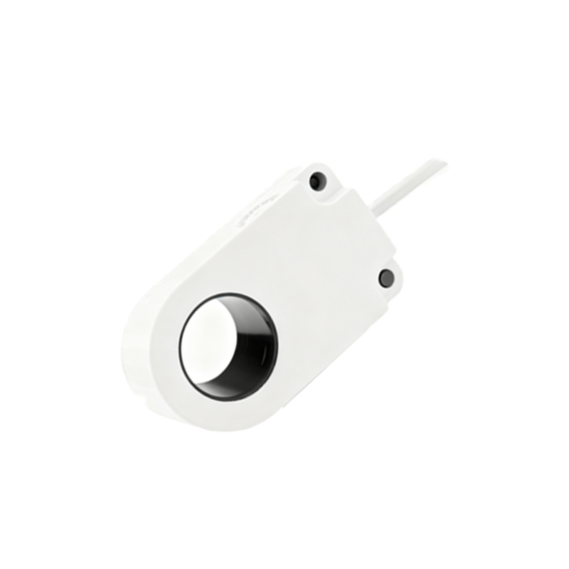
PNP vs. NPN Sensor Color Distinctions
Despite sharing the same brown and blue wires for power, the functionality of the black output wire differs between PNP and NPN sensors, which is not indicated by color but by sensor type labeling. For PNP (sourcing) sensors, the black wire provides a positive signal to the load, such as a PLC input or relay. Conversely, for NPN (sinking) sensors, the black wire acts as a path to ground when activated. It is critical to note that the wire colors themselves do not change with sensor type; misinterpreting this can lead to incorrect PLC programming or circuit damage. Engineers must always verify the sensor specification sheet to confirm whether it is PNP or NPN, as the color coding alone does not convey this information. This distinction impacts the overall control logic and wiring to interface devices.
Exceptions and Manufacturer Variations
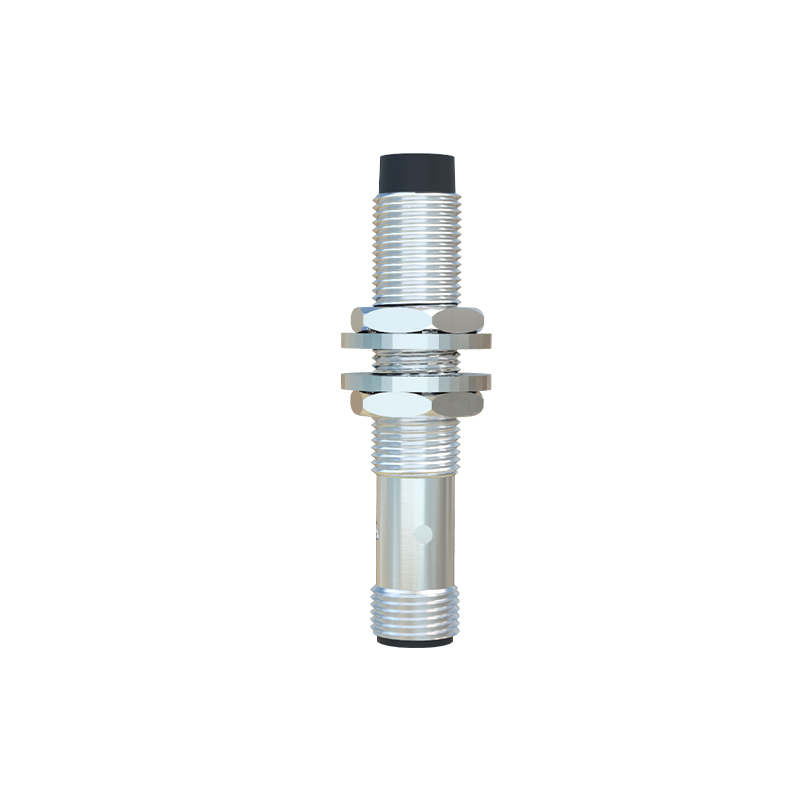
While the brown-blue-black standard is dominant, exceptions arise based on regional practices or specific manufacturer designs. For instance, some European or Asian brands might use alternative colors, such as red for positive, white for output, or green/yellow for ground in certain models. Additionally, sensors with analog outputs or IO-Link communication may incorporate extra wires with unique colors like gray or violet. Always consult the product datasheet or manual before installation. In cases where color codes deviate, clear labeling on the sensor body or cable is typically provided. Ignoring these variations can result in malfunction or hazardous situations, emphasizing the need for thorough pre-installation checks in diverse industrial environments.
Practical Installation and Troubleshooting Tips
When installing a 3-wire proximity sensor, first identify the power source polarity and match the brown wire to positive and blue to negative. Connect the black wire to the intended input device, ensuring the sensor type (PNP/NPN) aligns with the control system requirements. Use a multimeter to verify voltages: with power applied and no target present, the black wire should measure near 0V for PNP or supply voltage for NPN; detection should flip these states. Common issues, like no output signal, often stem from reversed power connections or mismatched sensor types. If colors are non-standard, trace wires back to labeled terminals. Regular maintenance includes checking for wire insulation damage and corrosion, as environmental factors can fade color distinctions over time.
Importance of Color Coding in Safety and Efficiency
Consistent color coding in 3-wire proximity sensors enhances operational safety by reducing electrical mishaps during installation or repair. It streamlines training for technicians, who can quickly identify connections across different machinery, minimizing errors that cause production delays. In global supply chains, standardized colors facilitate easier integration of equipment from various sources, supporting interoperability. Moreover, clear color schemes aid in rapid troubleshooting, as faults can be isolated by visually inspecting wire connections. As industries advance toward smarter factories, maintaining such standards becomes even more vital for seamless automation and reducing costly downtime, underscoring the role of simple color