Introduction to Adjustment Sensitivity
Laser photoelectric sensors are renowned for their precision in industrial automation, yet they are frequently reported to fail during or after adjustment procedures. This susceptibility stems not from inherent design flaws but from the intricate interplay between their high-precision components and the operational environment. Unlike simpler mechanical sensors, these devices rely on finely aligned optical paths and sensitive electronic circuits. Even minor deviations during calibration can push components beyond their tolerance limits, leading to premature failure. Understanding this vulnerability requires a deep dive into the core mechanisms and common missteps in handling.
Optical Misalignment and Collimation Issues
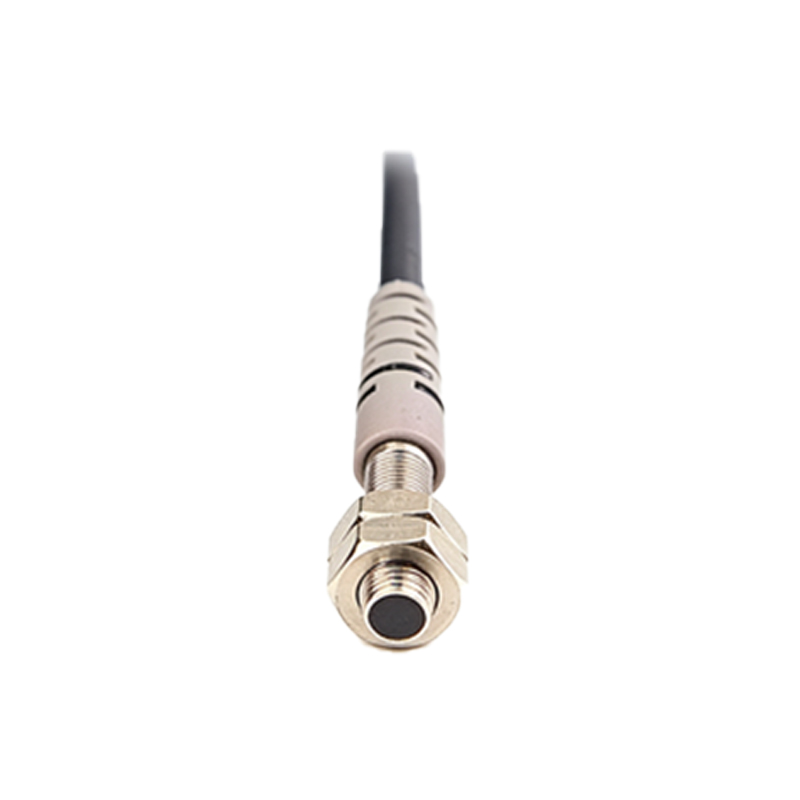
The heart of a laser sensor's functionality lies in its perfectly collimated beam. During adjustment, especially in field installations, technicians may attempt to realign the emitter and receiver manually. The laser diode and the receiving lens or phototransistor must be in precise coaxial alignment. Any physical shock, over-tightening of mounting brackets, or thermal expansion mismatch can cause micro-misalignments. These misalignments force the sensor to operate at the edge of its specification. The laser diode may be driven harder to compensate for a weaker received signal, increasing its junction temperature and accelerating the degradation of its semiconductor material, a primary failure mode.
Electrical Overstress During Calibration
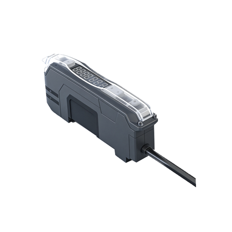
Modern sensors often feature potentiometers or digital interfaces for setting sensitivity, response time, and output logic. A common error is applying incorrect supply voltage or subjecting the sensor to voltage spikes from the control system during live adjustment. The integrated circuitry, particularly the amplifier stage that boosts the weak photocurrent, is highly sensitive. Exceeding the common-mode input voltage range, even briefly, can cause latch-up or electrostatic discharge (ESD) damage. Furthermore, repeatedly adjusting the sensitivity potentiometer to its extreme limits can wear out the wiper contact, introducing noise and eventual open circuits.
Environmental Contaminants and Lens Fouling
Adjustment often necessitates exposing the sensor's interior or temporarily removing protective housings. In industrial settings, this invites airborne contaminants like oil mist, dust, or metal shavings to settle on the critical optical surfaces. A speck of dust on the laser emitter's output lens can scatter the beam, drastically reducing its effective range and signal-to-noise ratio. Subsequently, an operator might incorrectly interpret this as a need for higher gain adjustment, straining the electronics. The contaminants can also be hygroscopic, leading to condensation and corrosion on PCB traces over time, a failure that manifests long after the adjustment was made.
Mechanical Resonance and Vibration Damage
The adjustment process itself can compromise the sensor's mechanical integrity. To achieve a stable mounting, technicians may use tools that impart high-frequency vibration or impact. Many laser sensor components, such as crystal oscillators for timing or fragile solder joints on surface-mount devices, are susceptible to resonance fatigue. A mounting bracket tightened under tension can also transmit more ambient machine vibration to the sensor's core. This mechanical stress can crack ceramic substrates, break wire bonds inside ICs, or loosen internal connectors, leading to intermittent operation or complete failure.
Software and Configuration Errors
With the rise of smart sensors featuring serial communication or IO-Link, software-based adjustment is common. Incorrect configuration parameters can be as damaging as physical mishandling. Setting an excessively fast response time for a slow-moving object may cause the sensor's internal processor to over-sample, increasing thermal load. Configuring incorrect output modes (e.g., NPN vs. PNP) can lead to wiring shorts. A "restore defaults" command might load a factory calibration unsuitable for the specific application, forcing hardware to operate in an unsustainable regime. These software-induced conditions create electrical stresses that accumulate, degrading component lifespan.
Preventive Measures and Best Practices
Mitigating adjustment-related failures requires a disciplined protocol. Always power down the system before making mechanical or wiring changes. Use manufacturer-recommended fixtures and tools for alignment. Employ a regulated power supply during initial bench testing. Keep protective caps on optical ports until the moment of final alignment. When adjusting parameters, make incremental changes while monitoring the output with an oscilloscope or meter, avoiding extreme settings. Ensure the operating environment (temperature, humidity, contaminants) is within the sensor's published specifications before and after adjustment. Implementing these best practices transforms adjustment from a failure risk into a reliable step for optimal performance.