Introduction to Photoelectric Sensors
Photoelectric sensors are widely used in industrial automation for detecting the presence, absence, or distance of objects without physical contact. These sensors operate by emitting a light beam, typically from an LED or laser diode, and detecting changes in the received light intensity. Among various configurations, the 4-wire photoelectric sensor is a common type that provides both output switching and power supply connections in a single compact device. This article delves into the circuit diagram and operational principles of a typical 4-wire photoelectric sensor, offering insights for engineers and technicians in the electrical and automation fields.
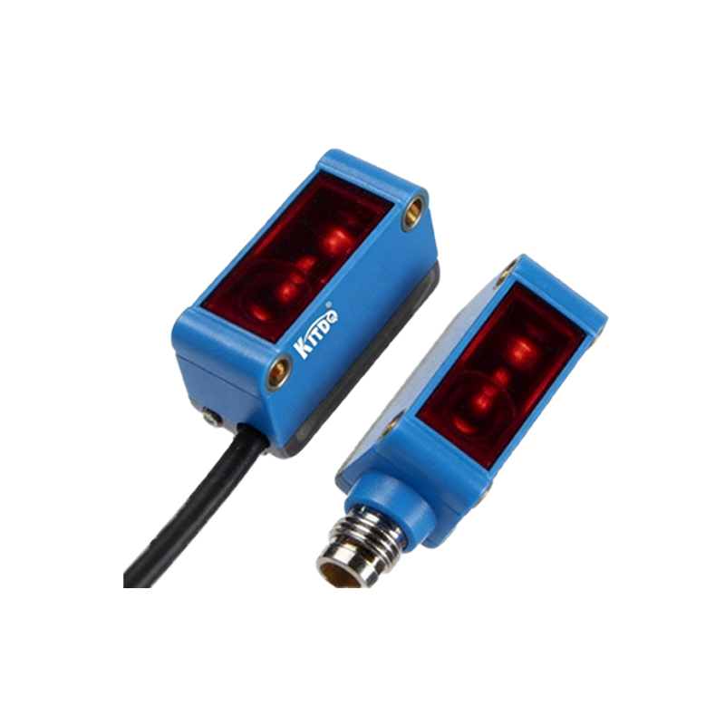
Basic Components and Wiring
A standard 4-wire photoelectric sensor consists of four distinct wires: two for power supply and two for output signals. The power wires are usually labeled as V+ (positive) and V- (negative or ground), connecting to a DC power source, commonly 12-24V DC. The output wires include a signal line and a common line, which interface with controllers like PLCs or relays. The circuit integrates an emitter section with a light source and a receiver section with a phototransistor or photodiode. When an object interrupts or reflects the light beam, the receiver detects the change, triggering the output circuit to switch states. This design allows for versatile mounting and integration in automated systems.
Internal Circuit Diagram Analysis
The internal circuitry of a 4-wire photoelectric sensor can be broken down into several key blocks. First, the power supply section includes voltage regulation and protection components, such as capacitors and diodes, to ensure stable operation and guard against reverse polarity or voltage spikes. The emitter circuit drives the LED or laser with a constant current source, often modulated to reduce ambient light interference. The receiver circuit amplifies the signal from the photodetector using operational amplifiers or transistors, converting it into a digital signal. Finally, the output stage features a solid-state switch (like a MOSFET or transistor) that toggles based on the received signal, providing either a normally open (NO) or normally closed (NC) contact. A typical diagram shows these blocks interconnected, with resistors setting sensitivity and capacitors filtering noise.
Output Types and Configurations
4-wire photoelectric sensors offer various output configurations to suit different applications. The most common are NPN (sinking) and PNP (sourcing) outputs, which define how the output signal is switched relative to the power supply. In an NPN output, the signal wire connects to the load, and the common line is grounded, causing the output to sink current when active. Conversely, a PNP output sources current from the positive supply. Additionally, sensors may provide analog outputs for distance measurement or digital outputs for simple on/off detection. The circuit diagram for each type includes specific transistor arrangements—for instance, an NPN output uses a bipolar junction transistor with its emitter tied to ground, while a PNP output uses a transistor with its emitter connected to V+. Understanding these differences is crucial for proper wiring and compatibility with control systems.
Practical Applications and Installation Tips
In industrial settings, 4-wire photoelectric sensors are employed in packaging, material handling, and assembly lines to detect objects, count items, or ensure proper positioning. When installing these sensors, engineers should consider factors like sensing range, environmental conditions (e.g., dust or moisture), and alignment. The circuit diagram aids in troubleshooting: for example, if the sensor fails to trigger, checking the power supply connections and output load with a multimeter can identify issues like short circuits or open wires. It's also important to follow manufacturer guidelines for wiring—ensuring correct polarity and using shielded cables to prevent electromagnetic interference. Regular maintenance, such as cleaning the lens and verifying signal stability, helps prolong sensor life and reliability.
Advantages and Limitations
The 4-wire design offers several advantages, including simplified wiring compared to 2-wire sensors, as it separates power and output circuits, reducing leakage current and improving accuracy. This allows for direct connection to programmable logic controllers (PLCs) without additional interfaces. However, limitations include higher cost and the need for more wiring, which can complicate installations in tight spaces. The circuit's complexity also means that repairs may require specialized knowledge. Despite this, the versatility and precision of 4-wire photoelectric sensors make them a preferred choice for many automation tasks, where reliable detection is critical for system efficiency and safety.
Conclusion and Future Trends
Understanding the circuit diagram of a 4-wire photoelectric sensor is essential for effective implementation in industrial automation. As technology advances, these sensors are evolving with features like IO-Link communication for smart factory integration, enhanced sensitivity adjustments, and miniaturization. Engineers should stay updated on these trends to optimize system designs. By mastering the electrical principles behind these devices, professionals can ensure robust and efficient automation solutions, contributing to improved productivity and reduced downtime in various industries.