Understanding Photoelectric Sensor Components
A photoelectric sensor is a critical device in industrial automation, used for detecting the presence, absence, or distance of objects without physical contact. Its core components include an emitter, which projects a light beam (often infrared, visible red, or laser), and a receiver, which detects changes in the received light signal. The housing protects the internal electronics and provides mounting options. The terminal block or connector is the key interface for wiring, typically featuring clearly labeled terminals for power supply, output signal, and sometimes auxiliary functions. Understanding these parts from a real-world image is the first step to correct installation. A close-up photo of a sensor's terminal strip, showing markings like "V+", "V-", "OUT", and "0V", provides immediate visual guidance far superior to a schematic alone.
Power Supply Wiring Connections
Providing stable power is fundamental. Most industrial photoelectric sensors operate on DC voltage, commonly 12-24V DC. The wiring involves connecting the positive lead from the power source to the sensor's positive terminal (often labeled V+, +V, or brown wire) and the negative lead to the negative terminal (labeled V-, COM, 0V, or blue wire). Polarity must be observed to prevent damage. A clear photograph of a sensor wired to a DC power supply, with red and black insulated wires securely fastened into the correct screw terminals, demonstrates proper practice. It's crucial to note that some AC-powered sensors exist, and their terminals (L and N) differ. Always verify the sensor's nameplate specifications against your power source before making any connections.
Output Signal Wiring Configurations
The output is how the sensor communicates its detection state to a controller like a PLC. The two primary types are NPN (sinking) and PNP (sourcing) for DC sensors, and relay or solid-state for AC/DC models. In a PNP configuration, the output terminal provides a positive voltage when an object is detected. This wire (usually black) connects to the input module of the PLC. For NPN, the output acts as a path to ground when active. A side-by-side comparison image showing the wiring of a PNP sensor to a PLC input (with the sensor's black wire going to the PLC's digital input and the common negative shared) versus an NPN setup is invaluable. Diagrams overlaid on photos of actual terminals and PLC racks eliminate confusion between these critical, yet often misunderstood, wiring schemes.
Wiring for Different Operating Modes
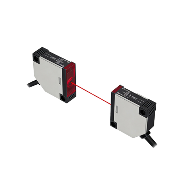
Photoelectric sensors function in three main modes: through-beam, retro-reflective, and diffuse (proximity). The wiring for power and output remains consistent, but the physical setup of emitter and receiver changes. For through-beam, the emitter and receiver are separate units wired independently to power. A photo showing two devices facing each other, with separate cables running back to a junction box, illustrates this. A retro-reflective sensor houses both elements in one unit and requires a reflector; its wiring is identical to a standard single-unit sensor. Diffuse sensors also use a single housing. Real installation images highlighting the alignment and cable routing for each mode provide practical context that pure text cannot.
Shielded Cable and Grounding Practices
In electrically noisy industrial environments, proper shielding and grounding are essential for reliable sensor operation. Many sensors have a dedicated grounding terminal or a shielded cable clamp. The shield, typically a braided or foil layer inside the cable jacket, should be connected to earth ground at the control panel end only, creating a drain for electromagnetic interference. A detailed photo of a sensor cable gland, where the shield is gathered and clamped to the metal housing of the sensor or a dedicated ground point, demonstrates best practice. Leaving the shield floating or grounding it at both ends can create ground loops and induce noise, leading to false triggering.
Practical Wiring Examples and Troubleshooting
Examining complete wiring examples solidifies understanding. Consider a common application: detecting boxes on a conveyor. A diffuse sensor is mounted overhead. A photo sequence could show: 1) The sensor secured on a bracket, 2) The conduit and cable entering a junction box, 3) Inside the box, wires from the sensor (brown/+, blue/-, black/output) connected to terminal blocks that distribute 24V DC from a power supply and route the output signal to a PLC input module. Accompanying this, a troubleshooting section with images can highlight common issues: loose terminal screws, pinched cables, incorrect NPN/PNP mismatch with the PLC input, or dirt obscuring the lens, all of which are easily identifiable through visual inspection of the physical setup.