Introduction to Photoelectric Sensor Wiring
Photoelectric sensors are fundamental components in modern industrial automation, providing non-contact detection of objects. Their operation relies on emitting a light beam and detecting changes in the received light intensity. A critical aspect of their implementation is the Input/Output (IO) wiring, which connects the sensor to a Programmable Logic Controller (PLC) or other control systems. Proper wiring ensures reliable signal transmission, system safety, and optimal performance. This guide details the standard wiring configurations, common connection types, and essential considerations for integrating photoelectric sensors into an industrial control circuit.
Understanding Sensor Output Types
The wiring diagram is primarily determined by the sensor's output type. The two main categories are Digital (Discrete) and Analog outputs. Digital outputs, the most common, provide a simple ON/OFF signal. These are further subdivided into two primary configurations based on the internal switching element: PNP (Sourcing) and NPN (Sinking). Analog outputs provide a continuous signal, such as 0-10V or 4-20mA, proportional to the detected distance or light intensity, but their wiring for power supply is similar to digital types. This article focuses on the wiring of digital output sensors, as they are the workhorse for standard detection tasks.
PNP (Sourcing) Output Wiring Configuration
A PNP output sensor sources current to the load. In this configuration, the positive voltage supply is switched. The typical wiring involves connecting the Brown wire (or L+) to the positive DC supply terminal (e.g., +24VDC). The Blue wire (or L-) connects to the common negative or 0V terminal. The Black wire is the switched output signal line. When the sensor detects an object, it internally connects the Black wire to the positive supply (Brown wire), sourcing current. This Black wire is then connected to the input channel of the PLC. The PLC input module's common must be connected to the negative supply (0V) to complete the circuit. This configuration is prevalent in European and many global standards.
NPN (Sinking) Output Wiring Configuration
An NPN output sensor sinks current from the load. Here, the negative supply path is switched. The power connections remain identical: Brown to +24VDC, Blue to 0V. The Black output wire, however, now connects internally to the negative supply (Blue wire) when active. To complete the circuit, the Black wire is connected to the PLC input. The corresponding common terminal on the PLC input module must be connected to the positive supply (+24VDC). When the sensor activates, it allows current to flow from the PLC input, through the sensor's output transistor, to the 0V line. This setup is commonly used in Asian and some North American applications.
Wiring to a PLC Digital Input Module
Connecting the sensor to a PLC requires matching the sensor's output type with the PLC input module's circuitry. Most modern PLC modules can be configured for either PNP or NPN sensing, often by wiring the common terminal appropriately. For a PNP sensor, wire the sensor's Black output to the PLC input point (e.g., I0.0). The common (COM) terminal of that input group is wired to 0V. For an NPN sensor, the sensor's Black output still goes to the PLC input point, but the common (COM) terminal must be wired to +24VDC. Mis-matching these will result in the input never activating. Always consult both the sensor and PLC hardware manuals for specific terminal designations and voltage ratings.
Wiring Diagrams for Different Operating Modes
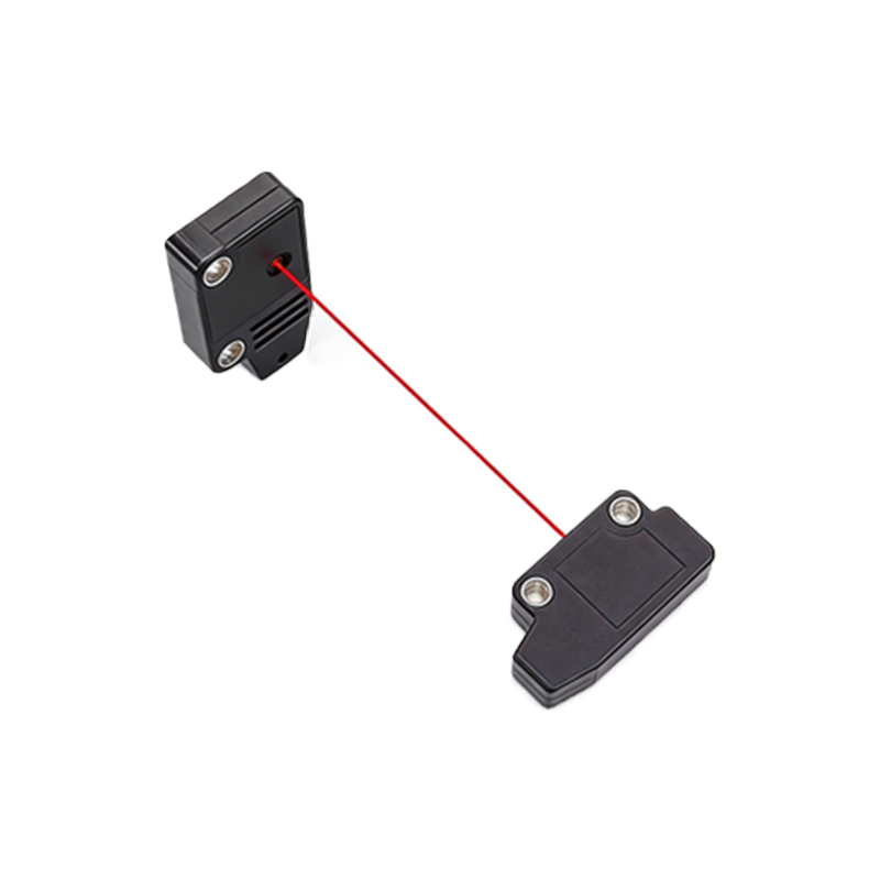
Photoelectric sensors come in three main operating modes: Through-Beam, Retroreflective, and Diffuse (Proximity). The wiring for the output is consistent across all modes; the difference lies in the physical setup of the emitter and receiver. A Through-Beam system has separate emitter and receiver units, each requiring power connections (Brown and Blue wires). Only the receiver unit will have the Black output wire. A Retroreflective sensor has both emitter and receiver in one housing, using a reflector. A Diffuse sensor also has a single housing, detecting light reflected directly from the target. The core power and output wiring for the single housing units is a standard three-wire or four-wire (if including a separate output) scheme.
Important Safety and Practical Considerations
Always disconnect power before beginning any wiring work. Use the correct wire gauge, typically 18-22 AWG for signal lines. Implement proper cable management and strain relief. For long cable runs, consider using shielded cables to prevent electrical noise interference, and ground the shield at one end only (usually the control panel end). Ensure the power supply voltage matches the sensor's rated voltage (commonly 10-30VDC). Include a fast-blow fuse in the positive supply line for protection. For sensors with diagnostic or teach-in functions, a fourth wire (often White or Gray) may be present; refer to the datasheet for its specific connection instructions to a digital input or separate interface.
Troubleshooting Common Wiring Issues
If a sensor fails to operate, systematically check the wiring. First, verify power at the sensor terminals using a multimeter. Confirm the Brown wire has +24VDC relative to the Blue wire. Next, check the output. For a PNP sensor, measure voltage between the Black and Blue wires; it should switch from near 0V to near +24V when an object is detected. For an NPN sensor, measure between the Black and Brown wires; it should switch from +24V to near 0V. If the sensor powers but the PLC does not register the input, verify the PLC common terminal wiring matches the sensor type. Also, check that the PLC input point is not damaged and is correctly addressed in the control logic.