Understanding 3-Wire Proximity Sensors
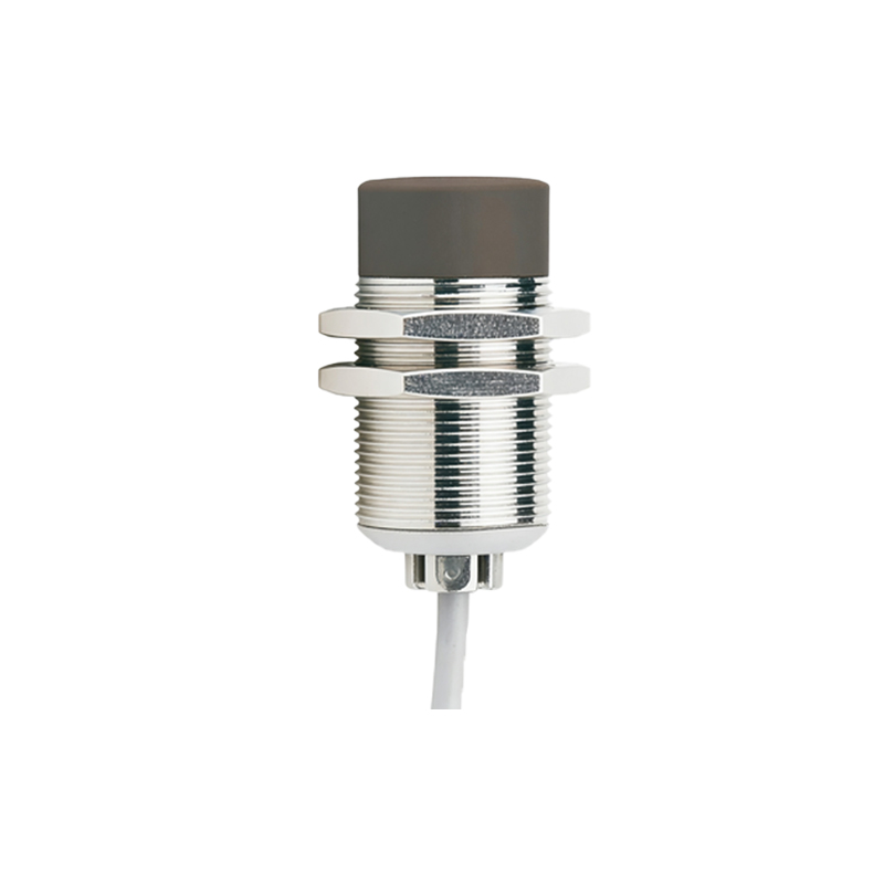
Three-wire proximity sensors are the most common configuration in industrial automation, offering a robust and reliable solution for object detection. Unlike two-wire sensors that are wired in series with the load, three-wire sensors provide separate paths for power supply and the switching signal. This design typically includes a brown wire for the positive DC supply voltage (often +24V DC), a blue wire for the common negative or 0V, and a black wire that serves as the output signal line. This independent output allows for both normally open (NO) and normally closed (NC) switching configurations, providing greater flexibility in control logic design. The clear separation of power and signal circuits is fundamental to achieving stable performance, especially when considering long-distance wiring scenarios where voltage drop and interference become critical factors.
Challenges of Long-Distance Wiring
Extending the distance between a proximity sensor and its controller, such as a PLC, introduces several electrical challenges that can compromise system reliability. The primary issue is voltage drop along the supply wires. As distance increases, the inherent resistance of the cable causes a reduction in the voltage actually reaching the sensor. A sensor rated for 24V DC might only receive 20V or less at its terminals, potentially causing it to malfunction or behave erratically. Secondly, long wires act as antennas, making the system more susceptible to electromagnetic interference (EMI) from nearby motors, drives, or power lines. This noise can induce false signals on the output wire, leading to erroneous triggering. Finally, capacitive and inductive effects in long cable runs can slightly delay signal transitions, which may be problematic in high-speed counting applications.
Key Principles for Reliable Long-Distance Operation
To ensure dependable operation over extended distances, specific design principles must be followed. First, correct cable selection is paramount. Using a cable with a larger conductor cross-sectional area (e.g., 1.5 mm² instead of 0.75 mm²) significantly reduces resistance and minimizes voltage drop. Shielded cables are essential for noise immunity; the shield, typically a braided or foil layer, must be grounded at only one end (usually the control panel end) to effectively drain away induced interference without creating ground loops. Secondly, understanding the sensor's specifications is crucial. Pay close attention to the "operating voltage range" and the "voltage drop" parameter. Some sensors are specifically designed with a wider operating range or lower minimum voltage requirement, making them more suitable for long-distance applications.
Wiring Configuration and Best Practices
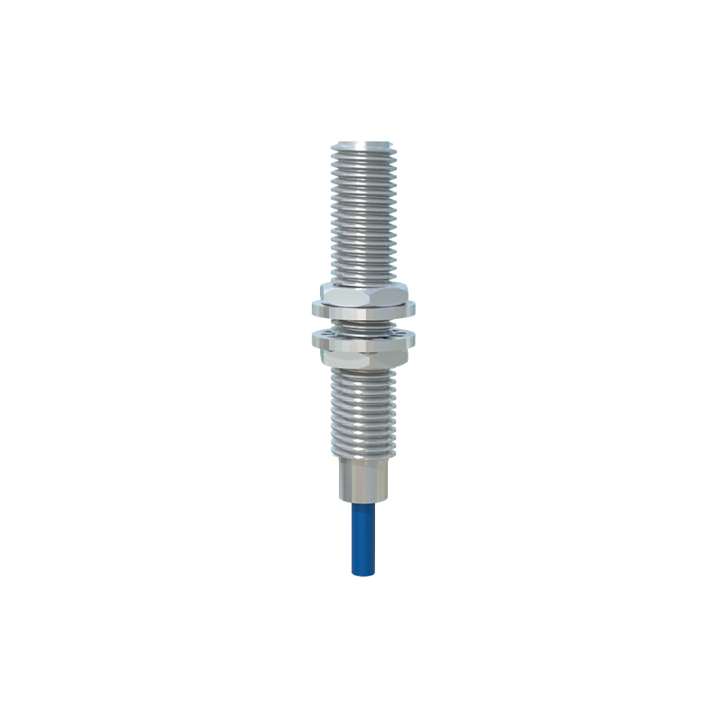
Proper installation is as important as component selection. For the power supply, it is often advisable to use a dedicated, well-regulated power source for long sensor runs, rather than sharing a heavily loaded common supply. The output load (the PLC input or relay) should be connected close to the controller. If the black output wire must run a long distance, consider its current-sinking or sourcing capability relative to the PLC input module's requirements. For very long runs exceeding 100 meters, intermediate signal conditioners or repeaters can be installed to boost the signal. All connections should be secure and protected from corrosion. The cable shield should be connected to a clean earth ground point at the control cabinet using a cable gland with an integrated shield clamp.
Advanced Solutions and Troubleshooting
When standard practices reach their limits, advanced solutions are available. For extreme distances or high-noise environments, converting the sensor's DC signal to a different format can be highly effective. Using an analog output sensor (4-20mA current loop) is inherently resistant to voltage drop and noise over long distances. Alternatively, a digital transmitter module can convert the switch signal to a protocol like IO-Link or AS-Interface, which is designed for robust long-distance communication. Common troubleshooting steps for long-wire installations include measuring the voltage directly at the sensor terminals under load, checking for continuity and insulation resistance of the cables, and using an oscilloscope to detect noise superimposed on the output signal. Always verify that the sensor's sensing distance is not marginally adjusted, as voltage drop can sometimes reduce its effective range.