Introduction to Proximity Switches in Pneumatic Systems
In the realm of industrial automation, the precise control and monitoring of pneumatic cylinders are paramount. Proximity switch sensors, often simply called proximity sensors, serve as the critical eyes of these systems. These non-contact electronic devices detect the presence or absence of a cylinder's piston without any physical touch. By providing a reliable electrical signal when the piston reaches a specific point in its stroke, they enable sophisticated sequencing, position verification, and safety interlocks. Their integration transforms a simple pneumatic actuator into a smart, feedback-rich component essential for modern assembly lines, packaging machinery, and robotic cells. The immunity to dust, oil, and other environmental contaminants makes them exceptionally robust for harsh industrial settings.
Operating Principles and Sensing Technologies
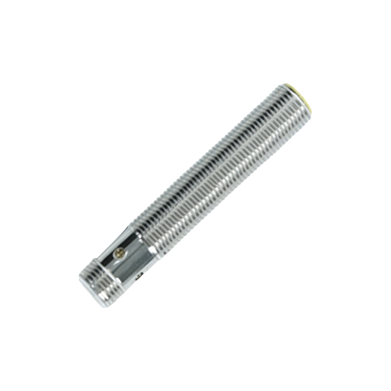
Proximity sensors for cylinders primarily utilize two fundamental technologies: inductive and magnetic sensing. Inductive proximity sensors generate an oscillating electromagnetic field. When a metallic object, typically the piston itself or a metal flag attached to it, enters this field, it induces eddy currents that dampen the oscillation. The sensor's internal circuit detects this change and triggers a switching output. Magnetic proximity sensors, or reed switches, operate differently. They contain ferromagnetic reeds sealed within a glass tube. When an external magnetic field, usually from a permanent magnet embedded in the piston, approaches, the reeds flex and make contact, closing the circuit. Each technology has its domain; inductive sensors are ideal for all-metal pistons, while magnetic sensors are indispensable for detecting non-metallic cylinders or where precise positioning of a small magnet is required.
Key Selection Criteria for Cylinder Applications
Choosing the correct proximity switch for a cylinder involves several critical parameters. First, the sensing distance, or switching distance, must be specified, ensuring reliable detection even with mechanical tolerances and misalignment. The construction and material of the cylinder body are vital; for example, non-ferrous stainless steel cylinders may require specialized inductive sensors or magnetic types. Environmental factors like temperature extremes, washdown conditions (IP67/IP69K ratings), and exposure to welding sparks or strong electromagnetic interference dictate the housing material and shielding. The electrical output type (PNP/NPN, NO/NC) must match the programmable logic controller (PLC) or control system input card. Finally, physical form factors, such as tubular, rectangular, or slot-style designs, must fit the cylinder's mounting provisions, like standard ISO 21287 or VDMA grooves.
Installation, Alignment, and Mounting Best Practices
Proper installation is crucial for optimal performance and longevity. The sensor must be securely mounted in its designated slot or bracket on the cylinder body. Precise alignment relative to the detection target (piston or magnet) is essential to achieve the rated sensing distance. For inductive sensors, the axial or lateral alignment with the piston must be within the datasheet specifications. For magnetic sensors, the orientation of the magnet's poles relative to the sensor is critical. Using mounting accessories like adjustable brackets or pre-wired connector systems can simplify installation and reduce wiring errors. It is also good practice to ensure that metal chips or other debris do not accumulate near the sensing face, as this could cause false triggering or damage.
Integration with Control Systems and Wiring Considerations
The output signal from a proximity sensor is typically a discrete 24V DC signal fed directly into a PLC's digital input module. Correct wiring is fundamental. A standard three-wire sensor requires connections for DC supply voltage (brown wire), ground (blue wire), and the switched output signal (black wire). Shielded cables are recommended in environments with electrical noise to prevent electromagnetic interference (EMI) from causing erratic signals. For diagnostics and troubleshooting, many modern sensors feature LED indicators that show power status and switching activity. In complex systems with numerous sensors, employing junction boxes or modular I/O blocks can streamline wiring and improve maintenance accessibility.
Troubleshooting Common Issues and Maintenance
Even robust proximity sensors can encounter issues. Failure to detect the piston may stem from incorrect sensor type (e.g., inductive sensor used on a non-metallic piston), excessive sensing gap, misalignment, or a failed magnet in magnetic systems. Constant activation might be caused by metal debris near the sensing face or a wiring short. Regular maintenance involves visual inspection for physical damage, cleaning the sensing face, and verifying the tightness of mounting hardware and electrical connections. Checking the output signal with a multimeter or the PLC's diagnostic software can quickly isolate faults to the sensor, wiring, or control system input.
Advancements and Future Trends
The evolution of proximity switch technology continues to enhance cylinder monitoring. Analog output sensors now provide continuous position feedback, not just end