Introduction to Slot-Type Photoelectric Sensors
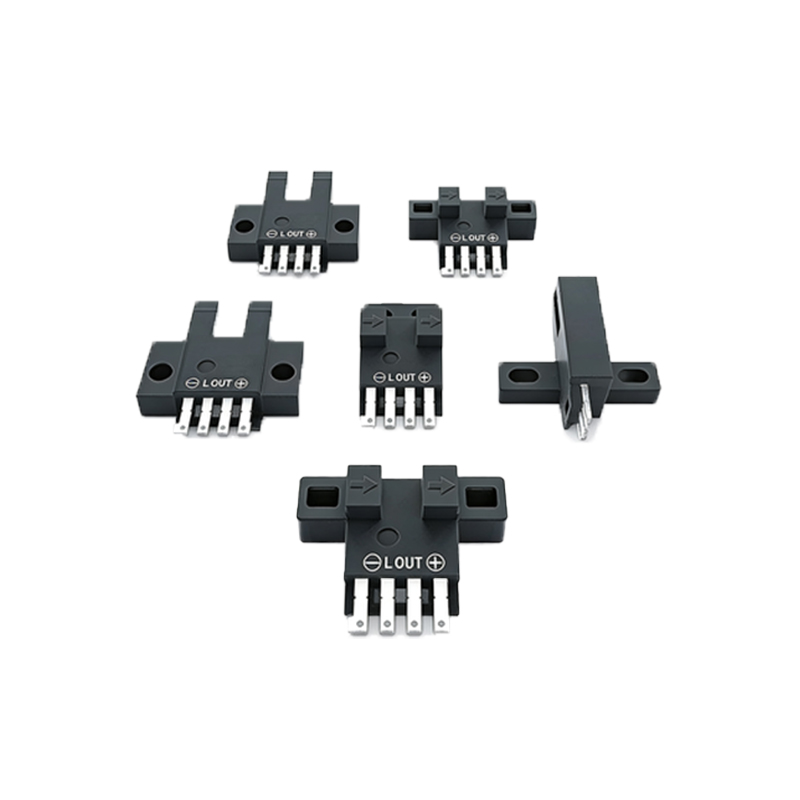
Slot-type photoelectric sensors, also known as through-beam sensors, consist of an emitter and a receiver housed in a single U-shaped body. The emitter projects a light beam across the slot to the receiver. When an object passes through the slot, it interrupts this beam, causing the sensor's output to change state. These sensors are widely used for object detection, counting, and position sensing in automation, packaging, and assembly lines due to their high precision and reliability. Their self-contained design simplifies installation compared to separate emitter-receiver pairs.
Understanding the Four-Wire Configuration
A four-wire slot sensor typically includes two wires for power supply and two for the output signal. This configuration is common for sensors with a transistor output, such as NPN or PNP types. The power wires, usually brown and blue, connect to the positive and negative DC supply terminals, respectively. The output wires, often black and white, provide the switching signal. The black wire is typically the output signal line, while the white wire may serve as a second output or a complementary signal, depending on the model. Always refer to the sensor's datasheet for exact wire functions, as color codes can vary by manufacturer.
Step-by-Step Wiring Procedure
First, ensure the power is off to prevent electrical hazards. Identify the sensor's wires using its documentation: brown for positive (V+), blue for negative (V- or 0V), black for output (OUT), and white for a second output or control line. Connect the brown wire to the positive terminal of a DC power source, typically ranging from 10-30V DC. Connect the blue wire to the negative terminal. For the output, link the black wire to the load (e.g., a PLC input, relay, or indicator). The white wire, if used, might connect to an additional input for functions like inverse logic or diagnostics. Secure all connections with appropriate terminals and insulate them properly.
Power Supply and Voltage Considerations
Slot-type photoelectric sensors require a stable DC power supply. Common operating voltages are 12-24V DC, but always check the sensor's rating to avoid damage. Ensure the power source matches the voltage and current specifications, typically below 100mA. Use a regulated power supply to minimize noise and voltage fluctuations, which can cause false triggering. For industrial environments, consider adding surge protection or filters to shield against electrical interference. Proper grounding of the power supply and sensor housing enhances reliability and safety, especially in high-noise settings like motor-driven systems.
Output Types and Load Connections
Four-wire sensors often feature transistor outputs, either NPN (sinking) or PNP (sourcing). For an NPN output, the black wire switches the negative side of the load; connect the load's positive side to V+. For a PNP output, the black wire switches the positive side; connect the load's negative side to V-. The white wire may provide a complementary output (e.g., normally open vs. normally closed) or a diagnostic signal. Verify the output current rating to ensure it can drive the connected load without overheating. For inductive loads like relays, use a flyback diode to protect the sensor from voltage spikes.
Testing and Troubleshooting Tips
After wiring, power on the system and test the sensor. Pass an object through the slot; the output should activate, indicated by an LED on the sensor or a response in the load. If it fails, check power connections with a multimeter to confirm correct voltage. Ensure the object is opaque enough to interrupt the beam, and clean the lens if dirty. Verify wiring against the datasheet, as reversed polarity can damage the sensor. For intermittent operation, inspect for loose connections or environmental factors like ambient light interference. Use shielded cables in electrically noisy areas to prevent false signals.
Applications and Best Practices
Four-wire slot sensors are ideal for precise detection tasks, such as in conveyor systems for counting bottles, detecting paper in printers, or positioning components in robotics. For optimal performance, install the sensor securely to avoid vibration-induced misalignment. Maintain a clean environment to prevent dust buildup on the optics. Regularly calibrate and test the sensor as part of preventive maintenance. When selecting a sensor, consider slot width, response time, and environmental ratings (e.g., IP67 for dust and water resistance). Proper wiring and installation extend sensor life and ensure consistent operation in demanding industrial applications.