Understanding the Core Principle
At the heart of an electromagnetic induction proximity sensor lies a fundamental physical law: Faraday's Law of Induction. The sensor typically consists of a coil wound around a ferrite core, forming an oscillator circuit. When an alternating current passes through this coil, it generates a high-frequency electromagnetic field around the sensor's active face. In the absence of a conductive target, this oscillator operates at a stable amplitude. However, when a metallic object enters this oscillating field, eddy currents are induced on the surface of the target. These eddy currents draw energy from the oscillator, causing a measurable reduction in its amplitude. This amplitude change is detected by a threshold circuit, which subsequently triggers a solid-state output switch, signaling the presence of the target. The key characteristic is that these sensors react specifically to conductive materials, primarily metals, making them highly selective.
Key Operational Characteristics and Advantages
Electromagnetic induction sensors offer a suite of features that make them indispensable in industrial automation. One of their primary advantages is non-contact detection, which eliminates mechanical wear and tear, ensuring a long operational life. They are renowned for their high switching frequency, capable of detecting rapidly moving objects on production lines. These sensors are inherently robust, often housed in metallic or rugged polymer casings with high Ingress Protection (IP) ratings, making them resistant to dust, moisture, oils, and coolants. They are largely immune to ambient light conditions and can function reliably in challenging environments where optical sensors might fail. Furthermore, they provide consistent performance regardless of surface color or reflectivity, focusing solely on the electrical conductivity of the target material.
Primary Industrial Applications
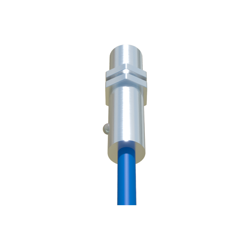
The application spectrum for inductive proximity sensors is vast within factory automation and machinery. A quintessential use is in position sensing and end-of-travel detection for cylinders, robotic arms, and slides. They are extensively deployed in conveyor systems to count metallic parts, control sorting gates, and verify the presence of components. In metalworking and CNC machinery, they serve as tool breakage detectors or spindle position monitors. Within assembly lines, they ensure parts are correctly positioned before a welding or riveting operation. They also play a critical role in rotary encoding, detecting gear teeth or bolts on a rotating shaft to monitor speed and position. Their robustness makes them ideal for harsh sectors like automotive manufacturing, metal stamping, and heavy machinery.
Critical Selection Parameters
Selecting the appropriate inductive sensor requires careful consideration of several technical parameters. The nominal sensing distance, or 'Sn', is the first criterion, defining the standard range at which a standard target can be detected. It is crucial to note that the actual sensing range can vary with different metals; for instance, it reduces for non-ferrous metals like aluminum or copper compared to steel. The sensor's housing style—barrel (cylindrical) or rectangular—must fit the mechanical constraints. The output type, whether NPN (sinking) or PNP (sourcing), must be compatible with the control system's PLC input card. Other vital specs include the operating voltage (commonly 10-30V DC), switching frequency, response time, and the required protection class (e.g., IP67, IP69K) for the environment.
Installation Considerations and Best Practices
Proper installation is paramount for reliable sensor operation. A primary consideration is maintaining adequate clearance. Flush-mountable sensors can be installed embedded in metal without loss of sensing range, while non-flush models require a free zone around the sensing face. Adjacent sensors must be spaced sufficiently apart to prevent mutual interference of their electromagnetic fields. The sensing face should be kept clean from buildup of metallic swarf or conductive debris, which could cause false triggering. Engineers must also account for temperature limits, ensuring the sensor is rated for the ambient operational temperature, especially in foundries or welding cells. Correct wiring, following the manufacturer's datasheet for brown (V+), blue (V-), and black (output) wires, is essential to prevent damage.
Future Trends and Technological Evolution
The evolution of electromagnetic induction sensors continues to align with Industry 4.0 trends. Modern sensors are becoming increasingly intelligent, incorporating IO-Link communication protocols. This digital interface allows for remote parameter setting, real-time diagnostics, and process data monitoring, such as reporting signal strength or temperature, enabling predictive maintenance. There is also a trend towards miniaturization, providing the same sensing performance in smaller packages for compact machinery. Furthermore, advanced models now offer enhanced immunity to electromagnetic interference (EMI) and welding fields, expanding their usability in electrically noisy industrial plants. The integration of these smart features transforms the simple proximity switch into a valuable data point within the connected factory ecosystem.