Introduction to Proximity Sensor Fundamentals
Proximity sensors are non-contact electronic devices designed to detect the presence or absence of an object within a specified sensing range without any physical contact. These sensors operate on various physical principles, primarily electromagnetic, capacitive, and inductive. In industrial automation, they are indispensable for tasks such as object detection, position verification, and counting. The core function revolves around generating an electrical signal when a target object enters the sensor's active field. This capability eliminates mechanical wear and tear associated with limit switches, enabling high-speed, reliable operation in harsh environments filled with dust, oil, or moisture. Understanding the underlying schematic is crucial for proper selection, integration, and troubleshooting in complex control systems.
Inductive Proximity Sensor Schematic and Operation
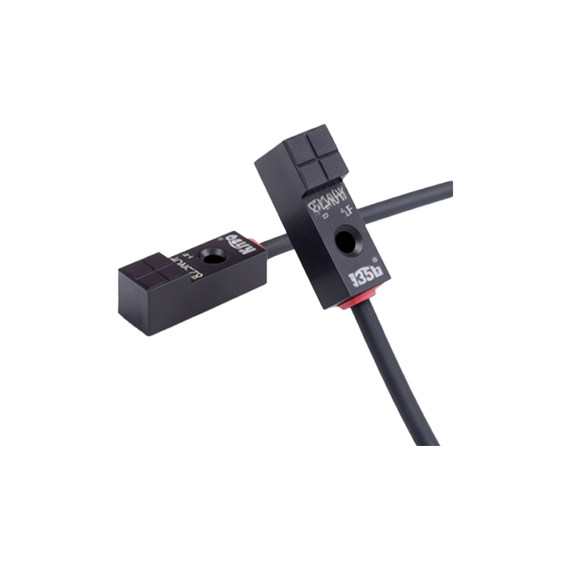
Inductive proximity sensors are the most common type, specifically used for detecting metallic objects. The internal schematic centers around an oscillator circuit, a detection coil, and a signal conditioning unit. The oscillator generates a high-frequency electromagnetic field that radiates from the sensor's active face, which is typically a wound coil. When a ferrous or non-ferrous metal object enters this oscillating field, eddy currents are induced on the surface of the target. These eddy currents draw energy from the oscillator, causing a measurable change in its amplitude. This amplitude reduction is detected by a threshold circuit within the sensor. Once the amplitude drop exceeds a predefined level, the sensor's solid-state output switch (typically NPN or PNP transistor) changes state, sending a signal to the programmable logic controller (PLC) or other control device. The schematic clearly shows the separation between the sensing oscillator stage and the output switching stage, often protected by voltage regulators and surge suppression components.
Capacitive Proximity Sensor Monitoring Circuitry
Capacitive proximity sensors can detect both metallic and non-metallic materials, including liquids, plastics, and wood. Their schematic is similar to inductive sensors but operates on the principle of capacitance change. The sensor face acts as one plate of a capacitor, with the target object acting as the other plate, and the air gap as the dielectric. An internal oscillator circuit is tuned so that it does not oscillate in its idle state. As a target object approaches, it alters the dielectric constant and increases the effective capacitance of the system. This change allows the oscillator to begin oscillating. The subsequent increase in amplitude is processed by a trigger circuit. The monitoring schematic includes sensitivity adjustment potentiometers, allowing engineers to fine-tune the sensing distance for different materials and to ignore background interference, such as container walls. This makes them ideal for level detection and material handling applications.
Output Configuration and Interface Schematics
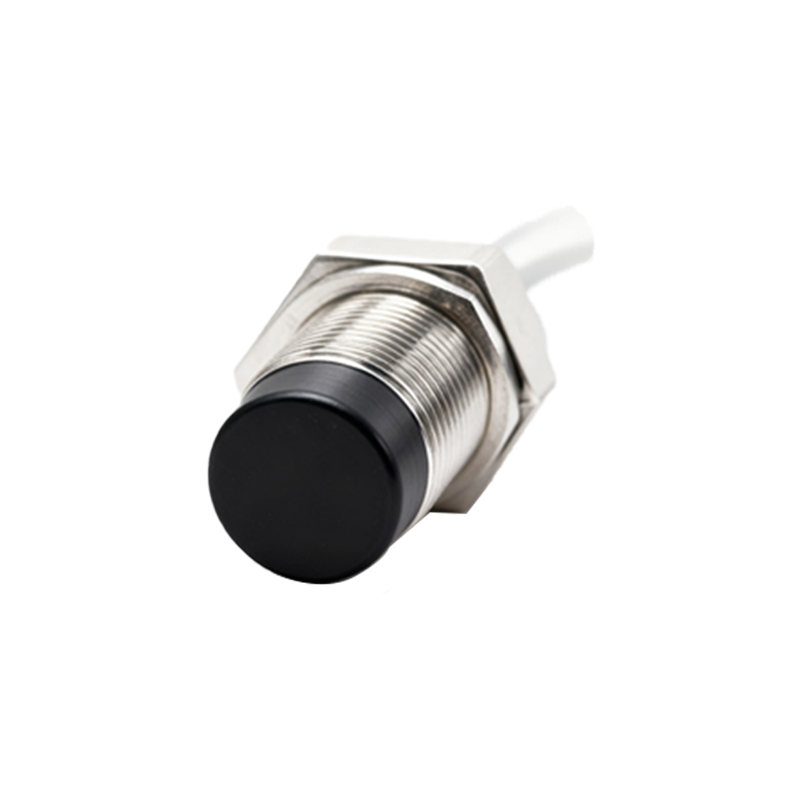
The output stage of a proximity sensor is a critical part of its monitoring schematic. Sensors are available in digital (switching) and analog (proportional) output configurations. The digital output, shown in the schematic as a transistor switch, is either normally open (NO) or normally closed (NC). This switch interfaces directly with PLC input modules. The schematic details the connection to the load (PLC), the power supply (typically 10-30V DC), and the necessary protective components like flyback diodes for inductive loads. Analog output sensors, such as 4-20mA or 0-10V types, incorporate an additional circuit that converts the sensed distance into a continuously variable signal. This schematic block includes a signal amplifier and a voltage-to-current converter, providing precise positional feedback for control systems, enabling applications like edge guiding or thickness monitoring.
Wiring Diagrams and System Integration
A complete monitoring schematic extends beyond the sensor itself to include the wiring diagram for integration into a control panel. A standard 3-wire DC sensor schematic shows connections for brown (V+), blue (V- or common), and black (output signal). For 2-wire AC/DC sensors, the schematic simplifies to two wires that carry both power and the switched signal. Key considerations in the system schematic include the use of sourcing vs. sinking inputs on the PLC, the placement of pull-up or pull-down resistors if required, and proper shielding for cables in electrically noisy environments. The schematic must also account for failsafe requirements, sometimes necessitating redundant sensor configurations or watchdog timer circuits in the PLC program to monitor sensor pulse integrity in high-speed counting applications.
Diagnostic Features and Advanced Monitoring
Modern proximity sensors incorporate diagnostic LEDs and short-circuit protection directly into their schematic. The LED, driven by a simple current-limiting resistor circuit, provides visual status indication. More advanced sensors feature IO-Link communication capability. Their schematic includes a microcontroller, a digital communication transceiver, and memory. This allows for remote monitoring of parameters like operating temperature, output switch cycles, and even internal