Introduction to Photoelectric Sensors and Arduino
Photoelectric sensors are indispensable components in modern industrial automation, robotics, and IoT applications. They operate on the principle of detecting changes in light intensity to sense the presence, absence, or distance of an object. Common types include through-beam, retro-reflective, and diffuse reflective sensors. Integrating these sensors with an Arduino microcontroller opens a world of possibilities for prototyping, testing, and deploying cost-effective sensing solutions. Arduino's simplicity, extensive library support, and robust hardware make it an ideal platform for engineers to interface with and program photoelectric sensors for diverse operational requirements.
Understanding Sensor Output Signals
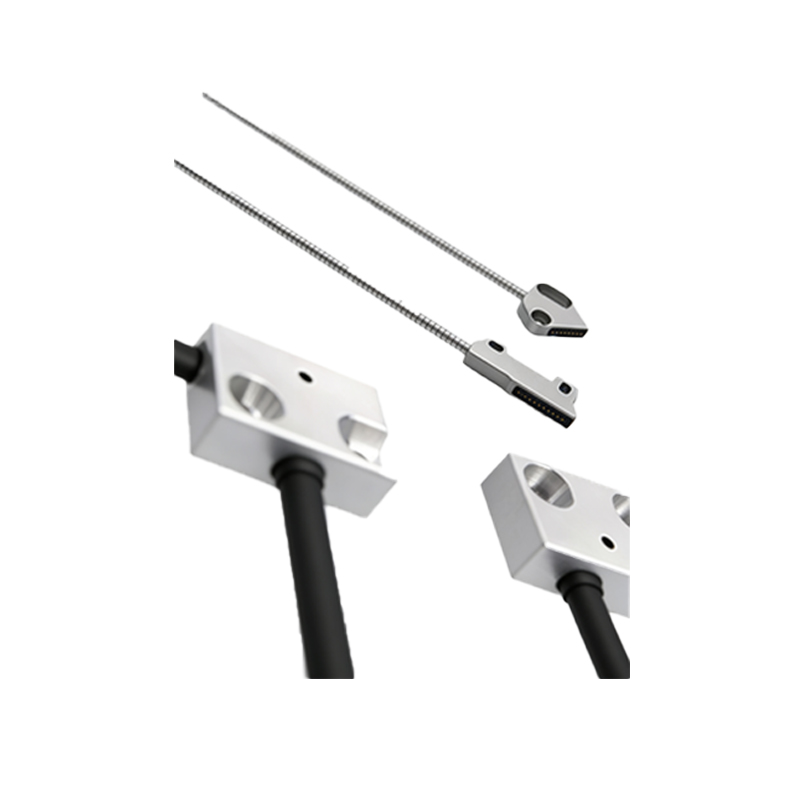
Before writing code, it is crucial to understand the electrical interface of the photoelectric sensor. Most industrial-grade sensors provide a digital output (e.g., NPN or PNP transistor) that switches state (HIGH/LOW) upon detection. Some advanced models offer analog output proportional to distance or light intensity. For Arduino, digital outputs can be read directly usingdigitalRead() on a designated pin. Analog outputs require connection to an Analog Input pin and the use ofanalogRead() to obtain a value typically between 0 and 1023. Always consult the sensor datasheet for voltage levels, current requirements, and connection diagrams to ensure compatibility and prevent damage to the Arduino board.
Basic Digital Detection Circuit and Code
A fundamental application is detecting the presence of an object. Connect the sensor's output wire (for an NPN type, the collector) to a digital pin on the Arduino, and the sensor's ground to the Arduino's GND. Power the sensor from an appropriate supply, often separate from the Arduino's 5V if current demands are high. The Arduino code is straightforward. First, define the sensor pin in thesetup() function usingpinMode(pin, INPUT). In theloop() function, continuously read the pin's state. A simple conditional statement can then trigger an action, such as turning on an LED or sending a serial message. This forms the core logic for conveyor belt counting, object sorting, or safety light curtain simulations.
Implementing Debouncing for Reliable Operation
In practical environments, sensor signals can be noisy due to electrical interference or rapidly changing environmental conditions, leading to false triggers. Software debouncing is essential to ensure reliable detection. Instead of acting on an immediate state change, the code should verify the signal remains stable for a short period. A common method involves reading the sensor state and, upon detecting a change, starting a timer (usingmillis()). The program only confirms the new state if it persists for, say, 50 milliseconds. This filter eliminates transient noise spikes, greatly improving the robustness of the application in industrial settings where reliability is paramount.
Reading Analog Sensors for Distance Measurement
Diffuse reflective sensors with analog output can be used for rudimentary distance sensing or detecting variations in surface reflectivity. Connect the sensor's analog output to an Arduino Analog Input pin (A0-A5). TheanalogRead() function returns an integer value. To convert this raw ADC value into a meaningful measurement, calibration is necessary. Map the sensor's output range to a known distance range using themap() function or a custom linear interpolation formula derived from empirical data. This calibrated value can then be used for tasks like material level monitoring, precise positioning, or differentiating between objects based on reflectivity, with results output to a serial monitor or display.
Advanced Techniques: Interrupts and Power Management
For high-speed applications or systems requiring efficient power usage, using hardware interrupts is superior to polling in theloop(). Attach an interrupt service routine (ISR) to the digital sensor pin usingattachInterrupt(). The ISR is called immediately when the pin state changes, allowing for near-instantaneous response, crucial for counting fast-moving items. Furthermore, to build battery-operated monitoring stations, consider power management. The photoelectric sensor and Arduino can be put into low-power sleep modes, waking only when the sensor detects a change via an interrupt. This dramatically reduces overall power consumption, enabling long-term, unattended operation in field applications.
Troubleshooting and Best Practices
Common issues include incorrect wiring, insufficient sensor power, and environmental light interference. Always use a multimeter to verify voltage levels. For optical interference, many sensors feature a potentiometer to adjust sensitivity; fine-tune this while observing the output. In code, implement comprehensive serial debugging to print sensor states, raw analog values, and timing information. Shield sensor cables in electrically noisy environments. Adhere to best practices such as using pull-up or pull-down resistors for digital inputs as needed, defining all connection pins as constants at the script's start for easy modification, and commenting code thoroughly for future maintenance and collaboration.