Introduction to Photoelectric Sensor Connectors
Photoelectric sensor connectors are critical components in industrial automation systems, serving as the vital link between the sensor itself and the control circuitry. These specialized connectors ensure reliable transmission of power and signal data, which is essential for the accurate detection of objects, distance, or presence. The performance of a photoelectric sensor is heavily dependent on the quality and suitability of its connector. A poor connection can lead to signal degradation, intermittent faults, or complete system failure, resulting in costly downtime. Therefore, understanding the types, specifications, and proper handling of these connectors is paramount for engineers and technicians designing, installing, and maintaining automated production lines, packaging machinery, and material handling systems.
Primary Types and Standards
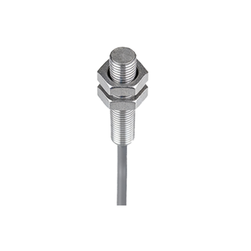
The market offers a variety of photoelectric sensor connectors, categorized mainly by their locking mechanism and pin configuration. The most common types include the M8 and M12 connectors, which are defined by their metric thread size. M12 connectors, with a 12mm diameter, are the industry standard for sensors, offering robustness and a secure screw-locking mechanism. They are typically available in 3-pin, 4-pin, or 5-pin configurations to accommodate different sensor functions (e.g., PNP/NPN switching, analog output, or IO-Link communication). M8 connectors, with an 8mm diameter, are used for more compact sensors where space is a constraint. Other types include quick-disconnect variants and specialized connectors for harsh environments. Adherence to international standards like IEC 61076-2 ensures compatibility and interchangeability between products from different manufacturers.
Key Selection Criteria
Selecting the correct connector requires careful consideration of several technical parameters. First, the electrical rating, including voltage and current capacity, must match the sensor's requirements. The pin count and wiring scheme (e.g., 3-wire DC) must be compatible. The ingress protection (IP) rating, such as IP67 or IP69K, indicates the connector's resistance to dust and water, which is crucial for washdown or outdoor applications. The housing material, often PBT plastic or metal, should be chosen based on chemical resistance and mechanical strength needs. For dynamic applications with continuous flexing, cables with PUR (polyurethane) sheaths and specialized strain relief are recommended. Finally, the connector gender (male on sensor, female on cable) and coding (A-coded for sensors, B-coded for fieldbus, etc.) must be verified to prevent mating errors.
Wiring and Installation Best Practices
Proper installation is non-negotiable for long-term reliability. Begin by carefully stripping the cable to the recommended length, ensuring no damage to the inner conductors. Follow the manufacturer's wiring diagram precisely; typically, brown wire is for DC+, blue for DC-, and black (or white) for the output signal. Use the correct crimping tool for the metal contacts to ensure a gas-tight, low-resistance connection. Insert the contacts firmly into the connector housing until they audibly click into place. Always employ the integrated strain relief clamp to absorb mechanical stress and prevent pull-out forces from reaching the electrical terminals. Before mating, inspect for bent pins or contamination. Tighten the coupling nut by hand until snug, avoiding over-torquing with a wrench which can damage the threads.
Common Faults and Troubleshooting
Even with quality components, issues can arise. Intermittent operation often points to a loose connection, damaged cable, or compromised strain relief. Check the tightness of the connector and inspect the cable for kinks or cuts. Complete failure may be due to incorrect wiring (e.g., reversed polarity), which can damage the sensor internally. Use a multimeter to verify voltage at the connector pins. Corrosion or moisture inside the connector housing, indicated by a low IP rating mismatch, will cause erratic signals. In communication-enabled sensors (IO-Link), faulty connectors are a common source of communication timeouts. Systematic isolation—testing the sensor with a known-good cable and connector—is the most effective troubleshooting method.
Future Trends and Advanced Features
The evolution of Industry 4.0 and IIoT is driving innovation in sensor connectivity. The widespread adoption of IO-Link protocol over standard M12 connectors is a significant trend, turning simple sensors into smart devices that transmit detailed diagnostic data. This necessitates 5-pin M12 connectors (A-coded or newly specified for IO-Link). There is also a growing demand for connectors with integrated LED indicators for quick status visualization. For extreme environments, connectors with higher sealing ratings and robust metal housings are becoming more prevalent. Furthermore, the push for tool-less field installation is leading to the development of push-pull or snap-in locking connector designs that reduce installation time while maintaining high performance.
Conclusion and Final Recommendations
Photoelectric sensor connectors, though small, play an outsized role in system integrity. A methodical approach to selection—matching type, pinout, IP rating, and material to the application—lays the foundation for success. Meticulous installation following best practices is equally critical. Investing in high-quality connectors and cables from reputable suppliers, rather than opting for the lowest-cost alternative, pays dividends in reduced maintenance and improved uptime. As systems grow smarter and more connected, specifying connectors that support advanced protocols like IO-Link will future-proof automation investments. Regular inspection of connectors as part of a preventive maintenance schedule can identify potential issues before they lead to production stoppages.