Introduction to UNITOP Photoelectric Sensors
UNITOP photoelectric sensors represent a pinnacle of reliability and precision in industrial automation. These devices utilize light beams to detect the presence, absence, or distance of objects without physical contact. Engineered for demanding environments, they offer superior performance across a vast spectrum of applications, from packaging and material handling to assembly line monitoring and safety systems. The core principle involves an emitter that projects a light beam and a receiver that detects changes in the received light signal. This non-contact method ensures minimal wear and tear, leading to extended operational life and reduced maintenance costs, making them an indispensable component in modern manufacturing and process control.
Key Features and Technical Specifications
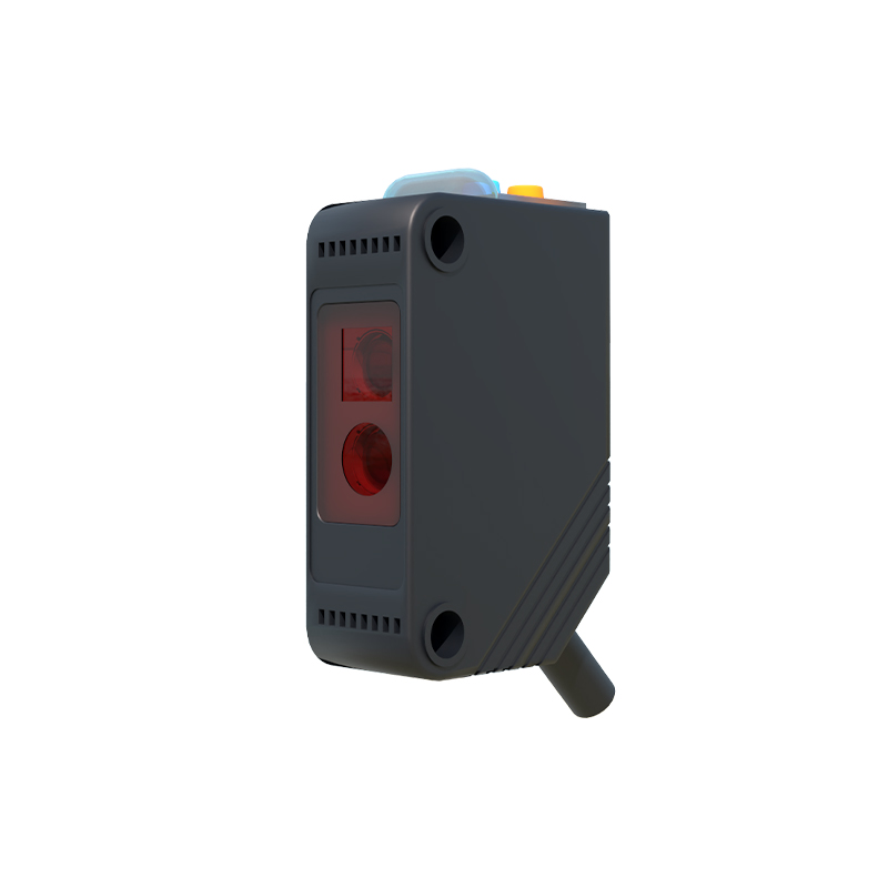
The UNITOP series is distinguished by its robust construction and advanced technological features. Key specifications include a wide operating voltage range, typically from 10-30V DC, ensuring compatibility with standard industrial power supplies. Models offer various sensing modes: through-beam, retro-reflective, and diffuse reflective, each suited for specific detection challenges. The sensors boast high switching frequencies, enabling detection of rapidly moving objects. Additional features often include adjustable sensitivity via potentiometers or teach-in functions, IP67 or higher ingress protection ratings for resistance to dust and water, and built-in diagnostics with stable operation indicators (LEDs). The housing is typically constructed from high-grade plastics or metals, providing resilience against mechanical impact and chemical exposure.
Installation and Mounting Guidelines
Proper installation is critical for optimal sensor performance. First, ensure the power is disconnected before wiring. Select a mounting location that provides a clear, unobstructed path for the light beam, considering the specified sensing range. Avoid mounting near strong ambient light sources, reflective surfaces, or vibrating machinery that could cause misalignment. Utilize the provided mounting brackets or standard M8/M12 mounting threads for secure fastening. For through-beam sensors, precise alignment of the emitter and receiver is paramount; use the alignment indicators. Maintain the recommended minimum and maximum distances between the sensor and the target object as per the datasheet. Always secure cables using cable glands or conduits to prevent strain and ensure environmental sealing.
Wiring and Electrical Connections
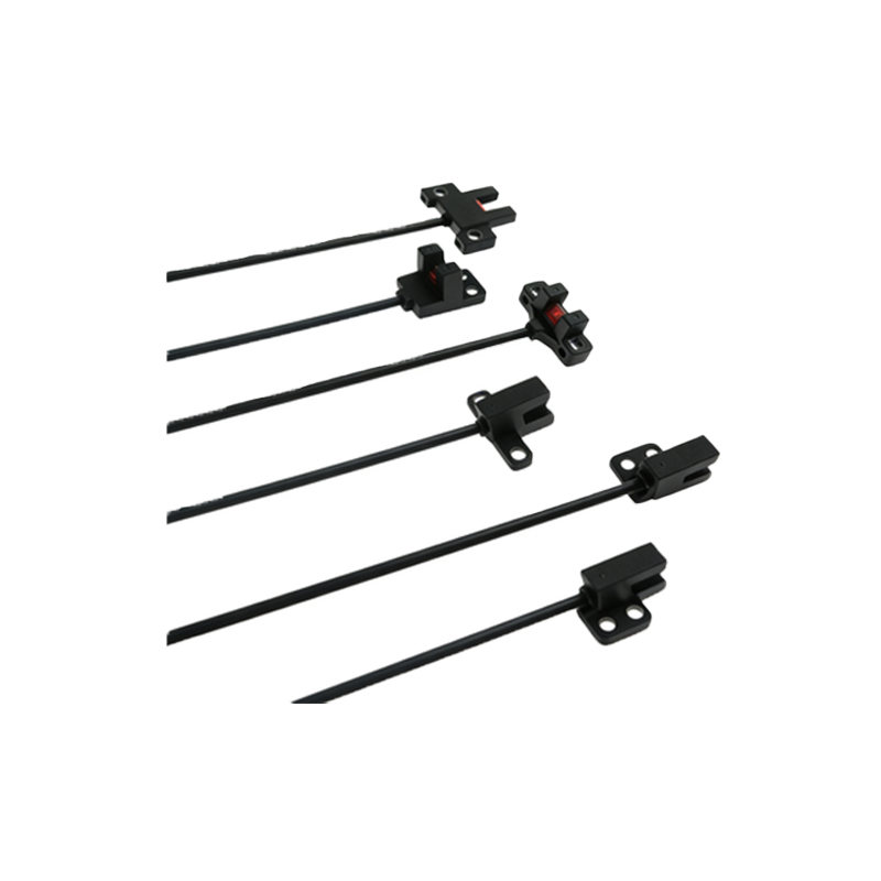
UNITOP sensors typically feature a standard 3-wire or 4-wire configuration. The common wire color coding is: brown for positive supply voltage (+V), blue for negative/common (0V), and black for the output signal (NPN or PNP switching output). Some models include a white wire for complementary output or control functions. It is imperative to connect the wires to the correct terminals on the programmable logic controller (PLC) or interface module, respecting the specified output type (sourcing or sinking). Always use shielded cables in electrically noisy environments and ground the shield at one end to the control panel earth to minimize electromagnetic interference. Refer to the specific model's wiring diagram printed on the housing or provided in the manual for absolute accuracy.
Operating Principles and Sensing Modes
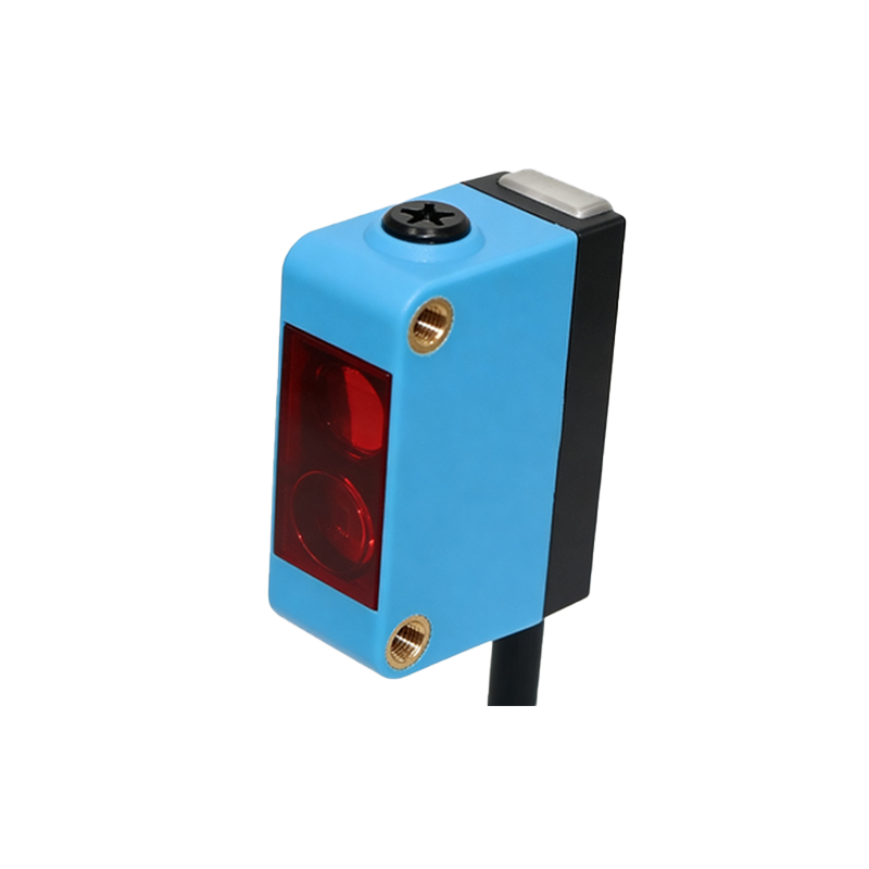
Understanding the three primary sensing modes is essential for correct application. Through-beam sensors consist of separate emitter and receiver units. Detection occurs when an object interrupts the beam traveling from emitter to receiver, offering the longest sensing range and highest reliability. Retro-reflective sensors house both emitter and receiver in one unit, using a reflector to bounce the beam back. An object is detected when it blocks this reflected beam. Diffuse reflective (proximity) sensors also have a single housing and detect light reflected directly off the target object. The effective range is shortest and depends on the target's color, material, and surface texture. Advanced models may feature background suppression or fixed-field background suppression for precise detection independent of object surface properties.
Configuration, Adjustment, and Calibration
Most UNITOP sensors allow for field adjustments to fine-tune performance. Sensitivity adjustment is the most common, achieved via a potentiometer or a teach-in button. For potentiometer models, rotate the screw to set the threshold; a clockwise turn usually increases sensitivity. Teach-in models simplify setup: present the target object at the desired detection distance and press the button to store the reference value. Some sensors feature a timing function (ON-delay/OFF-delay) adjustable via a second potentiometer. For precise applications, especially with diffuse sensors on challenging surfaces, perform calibration with the actual target object under normal operating conditions. Always verify the setting by testing with both the target object and potential non-target interferences.
Troubleshooting and Maintenance Procedures
Routine maintenance ensures long-term reliability. Periodically clean the lens with a soft, lint-free cloth to remove dust, oil, or debris that could attenuate the light signal. Inspect the housing and cable for physical damage. Common issues include no output signal, unstable operation, or shortened sensing range. Begin troubleshooting by checking the power supply voltage and polarity. Verify the alignment of through-beam or retro-reflective setups. Ensure the target object is within the specified sensing range and that its properties (size, color, material) are suitable for the sensor type. Check for excessive ambient light interference or the presence of optical obstructions like steam or fog. Consult the diagnostic LEDs: a stable light typically indicates power and alignment, while a blinking pattern may indicate a specific fault code as defined in the manual.
Safety Precautions and Compliance Standards
Adherence to safety protocols is non-negotiable. Always de-energize the system before installation, wiring, or maintenance. These sensors are components of machinery and do not replace primary safety devices like light curtains or emergency stops. Ensure the installation and application comply with all relevant local and international standards, such as IEC 60947-5-2 for proximity sensors, and machinery directives like CE, UL, or cUL. For use in potentially explosive atmospheres, only sensors with appropriate ATEX or IECEx certifications must be selected and installed according to the certification guidelines. The sensor's output should never be directly used to control hazardous energy without appropriate safety-rated relays or interfaces. Regularly review the entire control system's safety integrity.