Introduction to M12 3-Wire Proximity Sensors
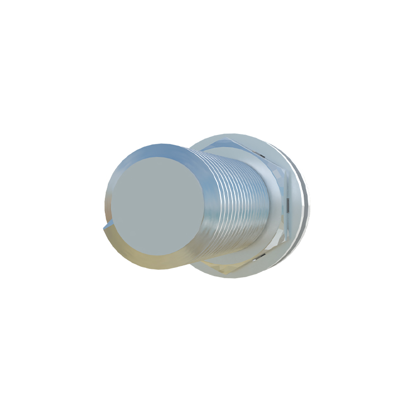
M12 3-wire proximity sensors are fundamental components in modern industrial automation, renowned for their reliability and compact design. These sensors utilize an electromagnetic field to detect the presence or absence of metallic objects without physical contact. The "M12" designation refers to the standardized 12mm threaded cylindrical housing, which ensures easy installation and robust environmental protection, typically rated at IP67 or higher. The 3-wire configuration is the most common in DC-powered sensors, providing a straightforward interface for integration into control systems. This design offers a balance of performance and simplicity, making it a preferred choice for countless applications in manufacturing, packaging, and material handling.
Understanding the 3-Wire Electrical Configuration
The core functionality of an M12 3-wire proximity sensor lies in its wiring scheme. The three wires are universally color-coded: brown for the positive supply voltage (V+), blue for the common negative or ground (0V), and black for the switched output signal. These sensors are primarily available in two output types: NPN (sourcing) and PNP (sinking). An NPN sensor switches the negative side of the load, common in Asian and some European systems, while a PNP sensor switches the positive side, prevalent in North America and much of Europe. This output wire carries the detection signal to a Programmable Logic Controller (PLC) or other control device. Proper understanding of this configuration is critical for correct circuit design and avoiding potential damage to the sensor or controller.
Key Operational Principles and Sensing Technology
M12 3-wire proximity sensors predominantly operate on the inductive sensing principle. Inside the sensor's face, an oscillator generates a high-frequency electromagnetic field. When a ferrous or non-ferrous metal target enters this field, it induces eddy currents that dampen the oscillation. This change is detected by a threshold circuit, which subsequently triggers the solid-state output switch. The sensing range, typically from 1 to 4 mm for standard M12 models, is a fixed characteristic determined by the sensor's design. Key performance metrics include repeatability, response frequency (how quickly it can detect objects passing by), and hysteresis (the difference between the switch-on and switch-off points), which collectively ensure stable and chatter-free operation in dynamic industrial environments.
Advantages of the M12 3-Wire Design in Harsh Environments
The combination of the M12 form factor and 3-wire electronics offers significant advantages. The threaded metal or rugged polymer housing provides excellent resistance to vibration, shock, and mechanical stress. The sealed connector interface protects against ingress of coolants, oils, and dust, ensuring longevity in demanding settings like machine tools or automotive assembly lines. Electrically, the 3-wire DC design is less susceptible to electrical noise compared to 2-wire AC/DC types, leading to more stable signal transmission. Furthermore, the availability of both shielded (flush-mountable) and unshielded versions allows for flexible installation adjacent to metal surfaces or in confined spaces, maximizing application versatility.
Typical Industrial Applications and Installation Best Practices
These sensors are ubiquitous in automation. Common applications include position detection of cylinders, end-of-travel limits on linear actuators, part presence verification on conveyor belts, and rotary speed monitoring. For optimal performance, installers must adhere to best practices. Ensure the sensor is mounted securely and aligned correctly with the target. Maintain the specified sensing distance, accounting for any reduction factors for non-ferrous metals. Always refer to the datasheet for the correct supply voltage (commonly 10-30V DC) and ensure the load current does not exceed the sensor's rated capacity. Proper wiring is essential; incorrect polarity can destroy the device. Implementing short-circuit and overload protection on the supply line is also a recommended safeguard.
Troubleshooting Common Issues and Maintenance Guidelines
Despite their robustness, issues can arise. Common problems include failure to detect, intermittent operation, or constant output. A systematic approach to troubleshooting involves checking the power supply voltage and polarity with a multimeter, verifying the target material and distance, and inspecting for physical damage or contamination on the sensing face. Ensure the load (e.g., PLC input) is functioning correctly. These sensors are generally maintenance-free, but periodic checks for accumulated metallic swarf or debris on the active surface are necessary. Avoid using them in environments with strong electromagnetic fields from welding equipment or large motors unless specifically rated for such conditions. Understanding the sensor's LED indicator status (power, output) is invaluable for quick diagnostics.