Understanding Photoelectric Sensor Basics
Photoelectric sensors are indispensable components in modern industrial automation, utilizing light beams to detect the presence, absence, or distance of objects. Optex, as a leading manufacturer, offers a diverse range of these sensors, including through-beam, retro-reflective, and diffuse-reflective types. Each type operates on a fundamental principle: a light emitter sends a beam, and a receiver detects changes in the received light intensity. The core functionality hinges on precise electrical connections. Incorrect wiring can lead to sensor failure, erratic machine behavior, or even damage to the control system. Therefore, consulting the specific wiring diagram for your Optex sensor model is not a suggestion but a mandatory step before installation. This guide provides a foundational understanding of common wiring configurations and terminal designations to ensure safe and effective implementation.
Deciphering Terminal Designations and Symbols
Before examining any wiring diagram, familiarizing yourself with standard terminal markings is crucial. An Optex photoelectric sensor typically features a cable or a connector with multiple colored wires or labeled terminals. Common designations include: Brown wire (or L+/+V) for the positive power supply, Blue wire (or L-/-V or COM) for the negative power supply or common ground, Black wire (or OUT) for the output signal (often NPN or PNP switching), and White wire (or OUT2) for a second output or control line. Some models may include a Pink or Gray wire for teach-in functions or diagnostic signals. The wiring diagram, usually found in the sensor's datasheet or on its housing, uses symbols to represent these terminals, the power source, and the load (e.g., a Programmable Logic Controller - PLC input, relay, or indicator). Always cross-reference the colors and labels physically present on your sensor with the diagram, as standards can vary by region and product series.
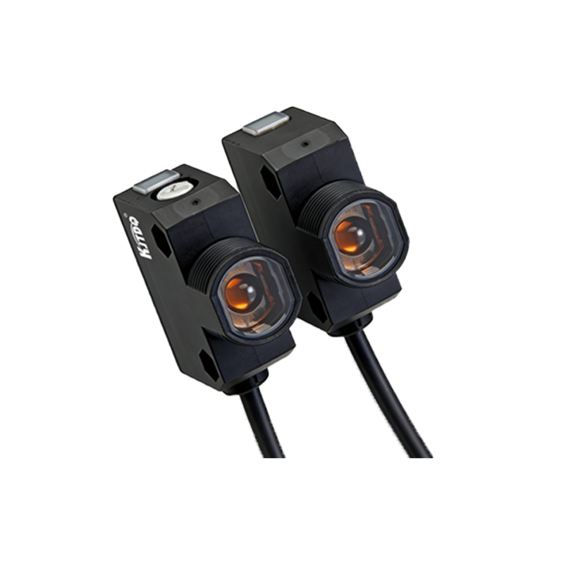
Standard Wiring Configuration for NPN Output Sensors
NPN output sensors are widely used, particularly in regions like Europe and Asia. In this configuration, the output transistor switches the negative or ground side of the load. Here is a typical wiring procedure: Connect the Brown wire to the positive terminal of your DC power supply (commonly 12-24V DC). Connect the Blue wire to the negative terminal of the same DC power supply. The Black wire (output) is connected to one terminal of your load device (e.g., the PLC input module). The other terminal of the load device is then connected back to the positive supply rail. When the sensor detects an object, the internal NPN transistor activates, creating a current path from the load, through the sensor's black wire, and out through the blue wire to ground. This completes the circuit, signaling the PLC. Ensure the load's operating voltage matches the sensor's supply voltage and that the current draw does not exceed the sensor's maximum switching capacity.
Standard Wiring Configuration for PNP Output Sensors
PNP output sensors are prevalent in North America and other markets. Here, the output transistor switches the positive voltage side of the load. The wiring differs accordingly: The Brown wire connects to the positive DC supply, and the Blue wire connects to the negative DC supply (ground), identical to the NPN setup. The critical difference lies in the output connection. The Black wire (output) is connected to one terminal of the load. The other terminal of the load is then connected directly to the negative supply rail (ground/blue wire). When activated, the PNP transistor connects the load to the positive supply (via the brown wire internally), allowing current to flow from the sensor's black wire, through the load, and to ground. This sinking configuration is essential to understand when interfacing with control equipment. Mismatching NPN and PNP sensors with incompatible PLC inputs is a common installation error that prevents proper operation.
Connecting to PLCs and Control Systems
Integrating an Optex sensor into a PLC system requires matching the sensor's output type with the PLC input type. Most modern PLCs have input cards that can be configured as either sinking (for PNP sensors) or sourcing (for NPN sensors). For a PNP sensor, the PLC input module should be set to sinking mode; the input point receives positive current from the sensor. For an NPN sensor, the PLC input should be in sourcing mode, providing positive voltage to the load, which the sensor then sinks to ground. Always disconnect power before making connections. Use the wiring diagram to identify the correct terminals on the PLC terminal block. Shielded cable is recommended for long cable runs or electrically noisy environments, with the cable shield grounded at one end (typically the control panel end) to prevent electromagnetic interference from causing false triggers.
Safety Precautions and Troubleshooting Tips
Adherence to electrical safety standards is paramount. Always de-energize the circuit before wiring. Verify the power supply voltage with a multimeter. Double-check that the wiring matches the diagram for your exact sensor model number (e.g., EX-20, FX-300). Common issues post-installation include no response: verify power connections, ensure the sensing object is within range and correctly reflects/interrupts the beam, and check for a mismatch between NPN/PNP sensor and load. Erratic operation often points to electrical noise; ensure proper shielding and grounding, and separate sensor cables from high-voltage power lines. If the sensor's indicator LED behaves abnormally, consult the manual for diagnostic blink codes. Never attempt to repair a damaged sensor; replace it with a certified unit. Proper wiring, as dictated by the official Optex wiring diagram, ensures reliability, longevity, and safety in your automated systems.