Introduction to Proximity Sensor Installation
Proximity sensors are critical components in industrial automation, enabling non-contact detection of objects. Proper installation is essential to ensure optimal performance, accuracy, and longevity. Incorrect mounting can lead to false triggers, reduced sensing ranges, or even sensor damage. This article explores various installation methods with diagrams to guide engineers and technicians in implementing these sensors effectively. Understanding the physical and environmental considerations is the first step toward reliable operation.
Flush Mounting (Embedded Installation)
Flush mounting involves installing the sensor so that its sensing face is aligned with the surrounding metal surface or mounting bracket. This method is commonly used for shielded or embeddable proximity sensors. The primary advantage is that it minimizes the risk of mechanical damage from passing objects. However, the sensing range is typically reduced compared to non-flush models. It is ideal for applications where space is constrained or where sensors must be protected from impacts. Diagrams often show the sensor recessed within a metal plate, with clearances specified to prevent interference from adjacent materials.
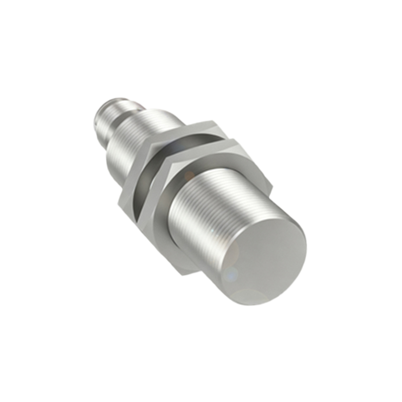
Non-Flush Mounting (Non-Embedded Installation)
In non-flush mounting, the sensor protrudes from the mounting surface, allowing for a longer sensing range. This style is typical for unshielded sensors. While it offers enhanced detection capabilities, the exposed sensor head is more vulnerable to physical collisions. Installation diagrams highlight the need for adequate space around the sensing area to avoid false detections from nearby metallic objects. This method is preferred in applications requiring extended range or where the sensor cannot be embedded due to material constraints.
Side-Mounting Configuration
Side-mounting refers to orienting the sensor laterally relative to the target's path. This approach is useful when direct frontal detection is impractical. Diagrams illustrate the sensor positioned perpendicular to the direction of object movement, often used in conveyor systems or guiding applications. Key considerations include aligning the sensing axis correctly and maintaining a consistent gap to ensure reliable operation. Side-mounting can reduce wear on the sensor face and is effective for detecting edges or specific features of objects.
Adjustable Bracket Mounting
Adjustable brackets provide flexibility in sensor positioning, allowing for fine-tuning of alignment and distance after installation. Diagrams depict slotted or pivoting brackets that enable easy adjustments without dismounting the sensor. This method is valuable in prototyping or applications where target positions may vary. It helps optimize sensing performance and accommodates tolerances in mechanical setups. Engineers should ensure brackets are securely fastened to prevent vibration-induced misalignment over time.
Multiple Sensor Array Installation
In complex automation systems, multiple proximity sensors may be installed in arrays to monitor several points simultaneously. Diagrams show sensors arranged in patterns, such as linear or grid formations, with attention to spacing to prevent crosstalk interference. Proper wiring and shielding are crucial to avoid signal degradation. This setup is common in packaging, sorting, and robotic cells, where coordinated detection enhances process control. Installation guidelines emphasize maintaining consistent mounting heights and orientations across the array.
Environmental Protection and Mounting Accessories
Environmental factors like dust, moisture, or temperature extremes necessitate protective measures. Diagrams include accessories such as mounting sleeves, protective caps, or enclosures that shield sensors from harsh conditions. For instance, in washdown environments, stainless steel housings with high IP ratings are recommended. Installation should ensure seals are intact and accessories do not obstruct the sensing field. Proper selection of materials and accessories extends sensor life and maintains reliability in demanding settings.
Wiring and Electrical Considerations
Electrical installation is as important as mechanical mounting. Diagrams illustrate wiring connections, including power supply, load, and grounding, following manufacturer specifications. Key points include using shielded cables to reduce electromagnetic interference, securing cable glands to prevent strain, and adhering to voltage and current ratings. Incorrect wiring can cause malfunction or damage. Always refer to datasheets for wiring diagrams specific to the sensor type (e.g., NPN vs. PNP outputs).
Maintenance and Troubleshooting Tips
Regular maintenance ensures sustained performance. Diagrams can highlight common issues, such as misalignment or buildup on the sensor face, with visual cues for correction. Installation practices should allow easy access for cleaning and inspection. Troubleshooting steps include verifying mounting stability, checking for environmental contaminants, and testing with targets at specified distances. Documenting installation layouts with diagrams aids in quick diagnostics and reduces downtime.
Conclusion
Selecting the appropriate installation method for proximity sensors depends on application requirements, space constraints, and environmental conditions. Diagrams serve as invaluable tools for visualizing setups and avoiding errors. By following best