Introduction to Photoelectric Sensor Symbols
Photoelectric sensors are widely used in industrial automation for detecting the presence, absence, or position of objects. Understanding their schematic symbols is crucial for engineers and technicians when designing, installing, or troubleshooting control systems. These symbols, standardized by organizations like IEC and ANSI, represent various sensor types and functions in electrical diagrams. This article explains common photoelectric sensor symbols, their meanings, and practical applications in circuit design.
Basic Components and Symbol Structure
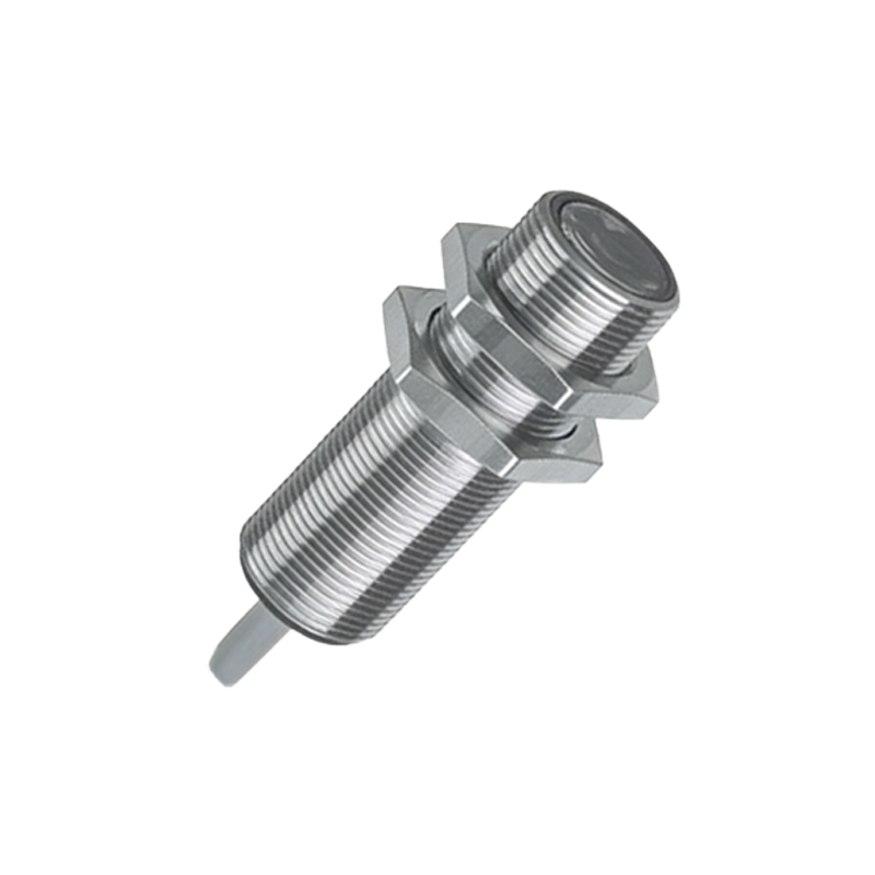
A typical photoelectric sensor symbol consists of a few key elements. The emitter is represented by a diode-like symbol with arrows pointing outward, indicating light transmission. The receiver, often shown as a phototransistor or photodiode symbol, includes inward-pointing arrows to denote light reception. These components are enclosed in a circle or square, representing the sensor housing. Additional markings, such as "Tx" for transmitter and "Rx" for receiver, may appear in detailed schematics. The symbols also include connection points for power supply, output signals, and sometimes adjustment terminals.
Through-Beam Sensor Symbols
Through-beam sensors, also called opposed-mode sensors, have separate emitter and receiver units. In schematics, the emitter symbol is placed on one side, with the receiver opposite it, often connected by dashed lines indicating the light beam path. The symbol typically shows a straight line between the two components, representing the uninterrupted beam. When an object interrupts this beam, the receiver's output changes state. These symbols are common in safety systems and high-precision detection applications, where alignment is critical for reliable operation.
Retroreflective Sensor Symbols
Retroreflective sensors combine emitter and receiver in one housing, using a reflector to bounce light back. Their symbol features both emitter and receiver elements within a single enclosure, with a curved or angled line pointing to a reflector symbol nearby. The reflector is often depicted as a small rectangle or triangle with a reflective surface indication. This symbol helps engineers identify sensors suitable for medium-range detection, where installing separate units is impractical. It's important to note that reflective targets may be shown differently in some diagrams.
Diffuse Reflective Sensor Symbols
Diffuse reflective sensors detect objects by measuring reflected light from the target itself. Their symbol shows emitter and receiver in one housing, with scattered lines or dots indicating diffuse reflection. Unlike retroreflective symbols, no separate reflector is shown. Instead, the symbol emphasizes the detection area with a cone-shaped pattern. These symbols are used in diagrams for applications where the sensor must detect objects without additional reflectors, such as in material handling or packaging systems.
Output Type Representations
Photoelectric sensor symbols also indicate output types through additional markings. A transistor output may be shown with a small "NPN" or "PNP" label near the output terminal. Relay outputs are represented by a switch symbol within the sensor enclosure. Analog output sensors include a wave or arrow symbol pointing to a variable resistance indicator. Some symbols incorporate logic function icons, like a timer symbol for sensors with delay functions. These details help engineers select appropriate sensors for specific control logic requirements.
Special Function Symbols
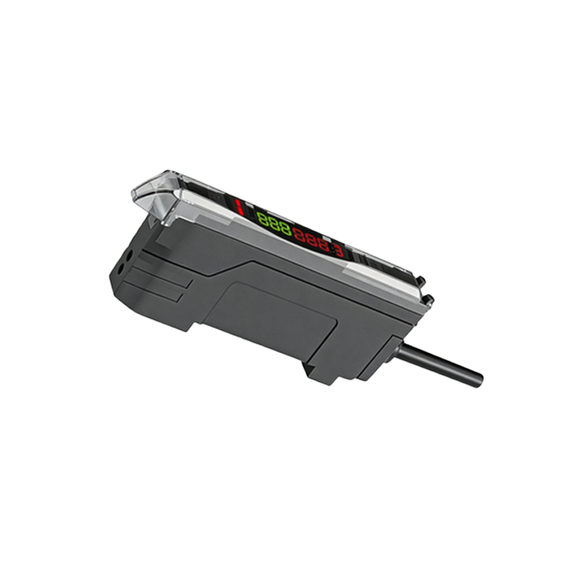
Advanced photoelectric sensors include special functions, represented by unique symbols. Background suppression sensors show a curved beam path with a suppression zone marking. Fiber optic sensors display a wavy line connecting to a separate amplifier symbol. Color recognition sensors include a prism or spectrum graphic. Safety-rated sensors feature an encircled "S" or shield symbol. Understanding these symbols ensures proper integration of specialized sensors for complex automation tasks, such as quality inspection or hazardous area monitoring.
Wiring and Connection Diagrams
Sensor symbols are often accompanied by wiring diagrams showing connection details. These diagrams use standard terminal markings: "V+" or "L+" for power supply positive, "V-" or "L-" for negative, and "OUT" for output signal. Shielded cable symbols may appear as dashed lines around connection lines. Some diagrams include load symbols, like a relay coil or PLC input, connected to the sensor output. Engineers must interpret these diagrams correctly to ensure proper voltage matching, load compatibility, and noise immunity in the final installation.
Common Mistakes in Symbol Interpretation
Misinterpreting photoelectric sensor symbols can lead to system errors. A frequent mistake is confusing NPN and PNP output symbols, causing incorrect PLC input wiring. Another error involves overlooking beam path indicators, resulting in misaligned sensor installation. Engineers should also verify symbol details against manufacturer datasheets, as some companies use proprietary variations. Always check for additional notes in diagram legends regarding sensor specifications, sensing ranges, or environmental ratings to avoid operational failures.
Practical Applications in Circuit Design
In circuit design, photoelectric sensor symbols help engineers plan control systems efficiently. For example, through-beam symbols might be used in conveyor line diagrams to indicate object counting stations. Retroreflective symbols could appear in door control systems for position detection. Symbols with timer functions are useful in automated assembly sequences. By correctly applying these symbols, engineers can create clear, standardized schematics that facilitate collaboration, maintenance, and system upgrades across industrial projects.
Conclusion and Best Practices
Mastering photoelectric sensor symbols enhances an engineer's ability to design and troubleshoot automation systems. Always refer to latest standards like IEC 60617 or ANSI Y32.2 for symbol updates. When creating diagrams, maintain consistency in symbol usage and include a legend for clarity. Cross-reference symbols with sensor manuals to confirm functionality. With accurate symbol interpretation, engineers can ensure reliable sensor integration, reduce downtime, and improve overall system performance in diverse industrial environments.