Understanding the Proximity Switch Indicator Light
In industrial automation, the status indicator light on a proximity sensor is a primary diagnostic tool. A solid or blinking light typically signifies that the sensor is powered and has detected a target within its sensing range. However, the core function of a limit switch is to provide a definitive electrical signal—often a change in state from normally open (NO) to closed (NC) or vice versa—to the control system (PLC, relay, etc.). The light being on confirms the sensing element is active, but it does not guarantee that the corresponding switching output is functioning correctly or that the signal is reaching the controller. This discrepancy between visual indication and functional output is the central issue when facing a "light on, no limit" scenario.
Primary Causes of Output Failure
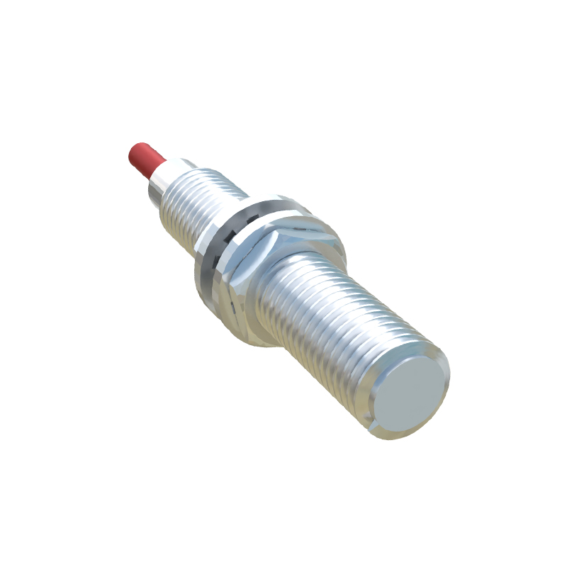
Several factors can interrupt the signal path between the sensor's internal detection and the final control command. A frequent culprit is a wiring fault. Loose connections, corroded terminals, or a broken wire in the output leg can prevent the signal from traveling to the PLC input module. Even with perfect sensor operation, an open circuit means no signal transmission. Another common issue is an incorrect load or short circuit. Exceeding the sensor's maximum switching current or voltage, or a downstream short, can damage the sensor's output transistor (in DC models) or triac (in AC models). This damage may be partial, allowing the indicator circuit to function while crippling the output stage. Power supply problems, such as voltage spikes or insufficient current, can also lead to this failure mode.
Sensor Configuration and Setup Errors
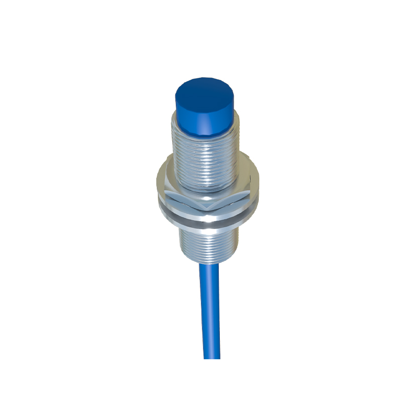
Improper installation and parameterization are significant contributors. The sensing distance may be incorrectly adjusted. If the target object is marginally within the sensor's maximum range, it might trigger the indicator light but produce an unstable or weak output signal that the controller cannot reliably interpret. For sensing different materials (e.g., aluminum vs. steel), failing to adjust the reduction factor or using a sensor not suited for the specific material can cause unreliable operation. Additionally, the physical alignment between the sensor and the target is critical. Angular misalignment or an off-center approach can reduce effective sensing distance, leading to intermittent or failed signaling even with a lit indicator.
Internal Component Degradation
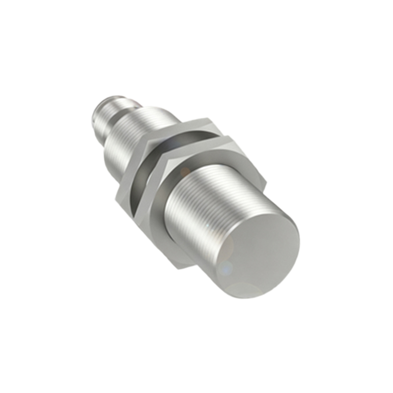
Over time, internal electronic components degrade. The oscillator, amplifier, and output circuitry within a proximity sensor are subject to thermal stress, vibration, and electrical wear. It is possible for the oscillator and detection circuit to remain functional enough to power the LED, while the final output switching component (like an NPN/PNP transistor) has failed. Environmental factors accelerate this process. Accumulation of metallic dust, conductive chips, or coolant fluid on the sensor face can create a false "detection" zone, keeping the light on but preventing proper sensing of the actual target. Extreme temperatures can also cause component drift, affecting output reliability before the indicator circuit fails.
Systematic Troubleshooting Procedure
A structured approach is essential for efficient diagnosis. First, verify the power supply at the sensor terminals with a multimeter to ensure it is within the specified range (e.g., 10-30V DC). Next, check the output signal independently. Disconnect the output wire from the PLC and use the multimeter to measure voltage (for PNP) or continuity (for NPN) between the output wire and the common terminal while actuating the sensor with the target. If the correct signal is present here, the fault lies in the wiring to the PLC or the PLC input card itself. If no signal is present at the sensor terminals, the sensor is faulty. Inspect the sensor face for contamination and ensure the target material, size, and approach meet the sensor's specifications.
Preventive Measures and Best Practices
Preventing this issue requires proactive maintenance and correct selection. Choose a sensor with a sensing distance 20-30% greater than the application requires to account for alignment tolerances and wear. Implement regular inspection schedules to clean sensor faces and check wiring integrity. Use surge protection devices on inductive loads to shield the sensor's output stage from voltage transients. For critical applications, consider sensors with separate, independently wired status LEDs for power and output state, providing a clearer diagnostic picture. Finally, always follow the manufacturer's guidelines for installation, wiring, and load specifications to ensure long-term reliability and avoid the confusing state of a lit sensor with no control action.