Understanding Proximity Switch Fundamentals
Proximity switches, also known as proximity sensors, are non-contact electronic devices designed to detect the presence or absence of an object within a specific sensing range. They operate on various principles, including inductive, capacitive, and magnetic (Hall effect or reed) technologies. Inductive sensors detect metallic objects, capacitive sensors can detect both metallic and non-metallic materials, and magnetic sensors respond to permanent magnets. The core function relies on generating an electromagnetic field or electrostatic field. When a target object enters this field, it causes a change in the oscillation amplitude or capacitance, which is then processed by the sensor's internal circuitry to trigger a switching output. This fundamental operation is key to understanding how sensitivity adjustments impact performance. The sensing distance, often referred to as the nominal range (Sn), is a critical parameter specified by manufacturers under standardized conditions. However, real-world applications often require fine-tuning this sensitivity to account for factors like target material, size, shape, and environmental interference.
Primary Methods for Sensitivity Adjustment
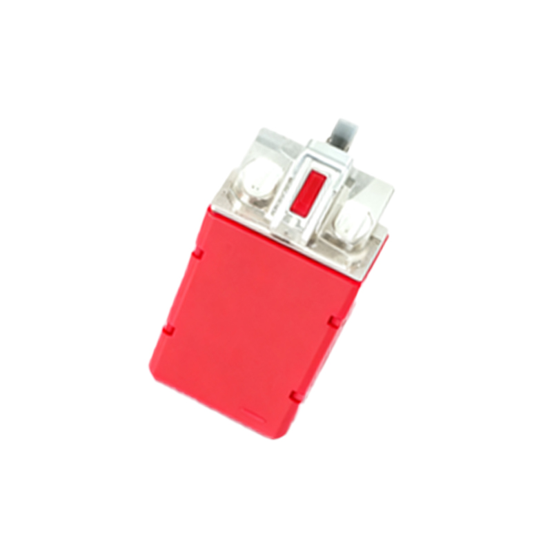
Most modern proximity switches come equipped with built-in mechanisms for sensitivity adjustment. The most common method is via a potentiometer, a small screw or dial located on the body of the sensor. Rotating this potentiometer changes the resistance in the sensor's circuit, thereby altering the threshold at which the output switches. Turning it clockwise typically increases sensitivity (lengthens the sensing distance), while turning it counterclockwise decreases it (shortens the sensing distance). Some advanced models feature teach-in functionality. This process usually involves presenting the sensor to the desired target at the required sensing distance and activating a programming button or sequence. The sensor then automatically learns and sets its trigger point. Another method, found in certain programmable logic controller (PLC) integrated systems, involves digital adjustment through software parameters, allowing for precise, remote calibration and monitoring of the sensor's operating point.
Factors Influencing Sensor Sensitivity
Several critical factors must be considered before and during sensitivity adjustment. The target material is paramount; for inductive sensors, ferrous metals like steel have a much longer effective sensing range than non-ferrous metals like aluminum or copper. The target size and shape also matter—a larger, flat surface perpendicular to the sensor face is ideal. A small or curved target may require increased sensitivity for reliable detection. Environmental conditions pose significant challenges. Extreme temperatures can affect electronic components and oscillation stability. The presence of other sensors in close proximity can cause mutual interference (cross-talk), leading to false triggering. Dust, moisture, and corrosive chemicals can coat the sensor's active face, attenuating the sensing field, particularly for capacitive sensors. Electrical noise from motors, variable frequency drives (VFDs), or welding equipment can also disrupt the sensor's signal, necessitating a sensitivity reduction for stability.
Step-by-Step Calibration Procedure
A systematic approach ensures accurate and reliable sensitivity tuning. First, consult the manufacturer's datasheet for the specific sensor model to understand its adjustment range and characteristics. Install the sensor securely in its final operational position. Power the sensor and connect its output to an indicator, such as a pilot light or a multimeter, to visibly confirm the switching state. Begin with the sensitivity potentiometer at its mid-range position. Introduce the standard target (as specified in the datasheet, typically a square of mild steel for inductive types) slowly towards the sensor face. Note the exact distance at which the output activates. To increase the operational sensing distance, slowly turn the adjustment screw clockwise until the output triggers at the desired, longer distance. To decrease it, turn counterclockwise. It is crucial to test with the actual application target, not just the test target. After adjustment, test the sensor's reliability by repeatedly moving the target in and out of the sensing zone at the required speed. Finally, check for false triggers by introducing potential interferers, like adjacent metal structures or other sensors, and adjust further if necessary.
Troubleshooting Common Sensitivity Issues
Even after careful adjustment, issues may arise. Intermittent operation or failure to detect often points to insufficient sensitivity for the specific target material or size, or an unstable power supply. Re-calibrate with the actual target and verify voltage levels. Conversely, if the sensor triggers without a target present or is triggered by nearby objects, the sensitivity is set too high. Reduce the sensitivity and investigate environmental factors like vibration, conductive dust buildup, or electrical noise. Shielding cables and ensuring proper grounding are essential steps to mitigate noise. For sensors that have worked previously but now malfunction, check for physical damage to the sensing face, wear of the potentiometer, or degradation due