Introduction to Proximity Sensor Spring Mechanisms
The spring mechanism within a proximity sensor is a critical, yet often underappreciated, component that directly influences sensor performance, longevity, and reliability. Unlike the sensing element or electronic circuitry, the spring's primary role is mechanical: to ensure consistent and precise positioning of the sensing face relative to the target, and to provide a secure, vibration-resistant mounting. In industrial environments characterized by shock, thermal cycling, and constant vibration, a well-designed spring structure is paramount for maintaining signal integrity and preventing false triggers. This guide delves into the technical aspects of proximity sensor spring structure diagrams, explaining their design principles, common configurations, and material considerations.
Core Functions of the Spring Assembly
The spring assembly in a proximity sensor fulfills several essential functions. Firstly, it provides axial compliance. During installation, the spring allows for minor misalignments or over-travel when the sensor is pressed into its mounting bracket, preventing damage to the sensor body or thread. Secondly, it ensures continuous electrical contact. In many threaded barrel-style sensors, the spring acts as a conductive path between the sensor housing and the metal mounting nut, which is often connected to ground (Earth). This is crucial for the sensor's shielding and EMI/RFI immunity. Thirdly, it mitigates the effects of thermal expansion. Different materials (sensor housing, mounting panel, target) expand at different rates; the spring accommodates these dimensional changes without inducing stress that could lead to failure.
Common Spring Structure Configurations
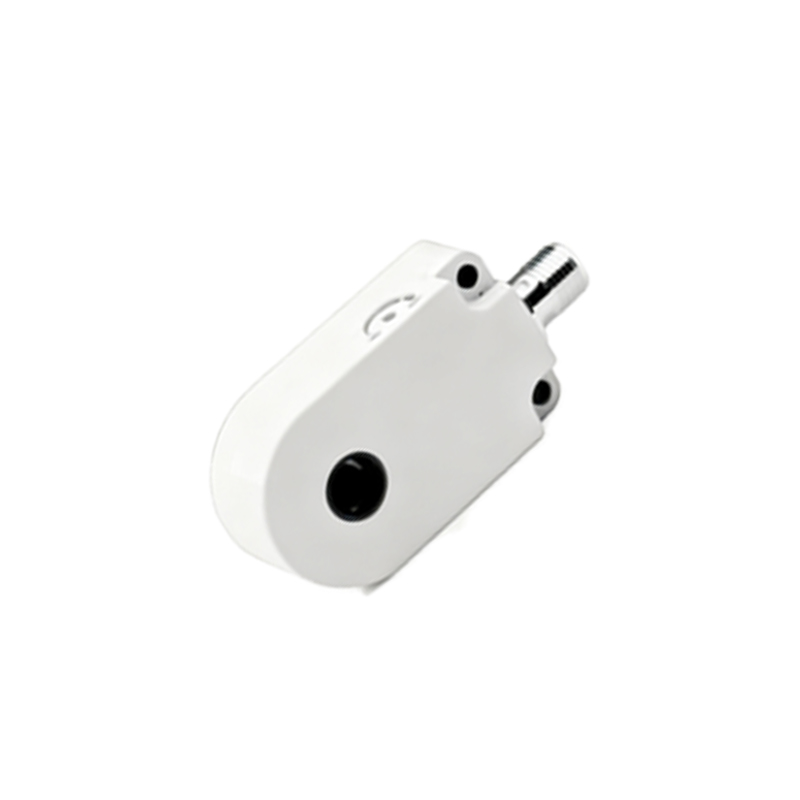
Analyzing a typical proximity sensor spring structure diagram reveals several standard configurations. The most prevalent is the helical compression spring located at the rear of the sensor housing, behind a movable collar or flange. This design allows the entire sensor body to move axially against spring pressure. Another configuration involves a Belleville washer (disc spring) stack. These conical washers provide a high spring force in a compact axial space, excellent for applications with high vibration. A third type uses a conductive elastomer or a spring-loaded pogo pin array. This design is common in rectangular or block-style sensors where the spring mechanism is integrated into the mounting feet or brackets, providing both damping and electrical contact.
Key Parameters in Spring Design
The design specifications extracted from a spring structure diagram are vital for application suitability. Spring Rate (k), measured in N/mm, defines the force required to compress the spring a given distance. A proper rate ensures secure mounting without being too stiff or too loose. Initial Tension is the pre-load force applied when the sensor is nominally installed. This keeps the sensor seated firmly. Maximum Deflection indicates how far the spring can be safely compressed without permanent set (plastic deformation). Material and Finish are also critical; music wire with zinc or nickel plating is common for corrosion resistance, while stainless steel is used in harsh environments. The Electrical Resistance of the spring path must be low to ensure effective grounding.
Interpreting a Spring Structure Diagram
A professional spring structure diagram is more than just a drawing of a coil. It includes detailed orthographic views (front, side, section) with precise dimensions. The sectional view is particularly important, showing the relationship between the spring, the sensor housing's inner shoulder, the movable collar, and the retaining circlip or snap ring. Critical callouts include the spring's free length, installed length, solid length (when coils are fully compressed), wire diameter, and mean coil diameter. Tolerances on these dimensions are strictly noted. The diagram will also specify the spring's orientation and its contact points with conductive and non-conductive parts.
Material Selection and Environmental Considerations
The operating environment dictates spring material choice. For standard factory automation, hard-drawn carbon steel wire with a protective coating suffices. In washdown (IP67/IP69K), chemical exposure, or outdoor applications, austenitic stainless steel (AISI 302/316) is mandatory for corrosion resistance, though it has a slightly lower spring rate. In high-temperature environments near ovens or furnaces, Inconel X-750 or similar high-temperature alloys may be required. The choice of material directly affects the spring's performance curve, fatigue life, and its ability to maintain contact force and electrical conductivity over time and temperature cycles.
Installation and Maintenance Implications
Understanding the spring structure informs proper installation and maintenance procedures. Installers must not bottom out the spring by over-tightening the mounting nut, as this can cause permanent set and loss of spring force, compromising vibration resistance and grounding. The diagram shows the correct installed length for this reason.