Introduction to Photoelectric Sensor Switches
Photoelectric sensor switches are pivotal components in modern industrial automation, offering non-contact detection of objects through light beams. These devices utilize a light emitter and a receiver to sense the presence, absence, or distance of targets, making them ideal for applications in manufacturing, packaging, and safety systems. Understanding their wiring is crucial for ensuring reliable operation and integration into control circuits. This guide provides a detailed overview of wiring diagrams, focusing on practical steps and common configurations to help engineers and technicians implement these sensors effectively. By mastering the wiring process, users can optimize sensor performance, reduce downtime, and enhance system efficiency in various industrial environments.
Key Components and Terminology
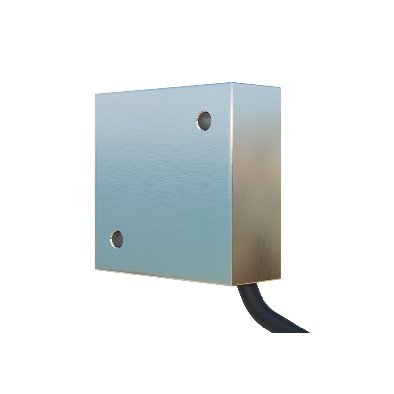
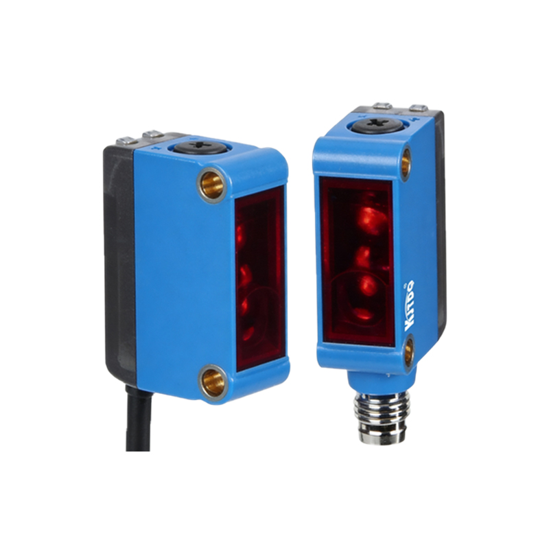
Before delving into wiring diagrams, it's essential to familiarize yourself with the core components of a photoelectric sensor switch. Typically, these sensors include a light source (often an LED), a phototransistor or photodiode receiver, and output terminals for connection to external devices. Common types include through-beam, retro-reflective, and diffuse sensors, each with distinct wiring requirements. Terminals usually consist of power supply pins (e.g., V+ and V-), output pins (e.g., NO/NC for relay or transistor outputs), and ground connections. Additionally, some models feature adjustable sensitivity or timer functions, which may involve extra wiring. Recognizing these elements ensures accurate interpretation of wiring diagrams and prevents errors during installation.
Standard Wiring Diagram Overview
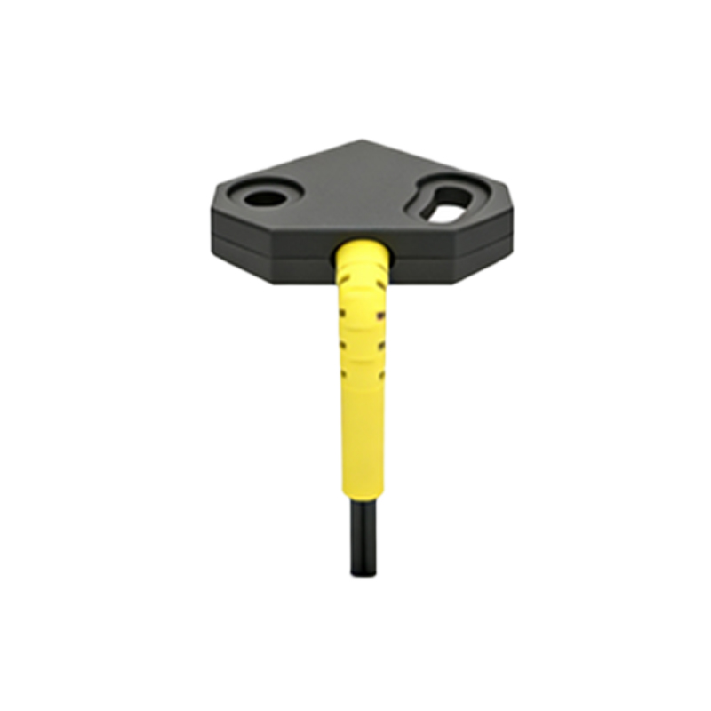
A typical photoelectric sensor switch wiring diagram illustrates how to connect the sensor to a power source and a load, such as a PLC (Programmable Logic Controller) or relay. For a basic two-wire DC sensor, the diagram shows the positive terminal linked to the power supply's positive side and the negative terminal to the load, which then connects to the supply's negative. Three-wire sensors, more common in industrial settings, include separate wires for power, ground, and output. The diagram often uses symbols: a circle for the sensor, lines for wires, and labels for voltages (e.g., 12-24V DC). Color-coding is standard, with brown for positive, blue for negative, and black for output. Following these diagrams step-by-step ensures safe and functional connections.
Step-by-Step Wiring Instructions
To wire a photoelectric sensor switch, start by disconnecting all power sources to prevent electrical hazards. Refer to the manufacturer's datasheet for the specific wiring diagram of your sensor model. For a three-wire NPN output sensor, connect the brown wire to the positive DC supply (e.g., +24V), the blue wire to the negative or ground, and the black wire to the input of the PLC or relay. If using a PNP output, the black wire typically connects to the positive side of the load. Secure connections with appropriate terminals or connectors, and avoid loose wires that could cause short circuits. Test the sensor by applying power and observing the output indicator LED; it should activate when an object interrupts the light beam. Always double-check connections against the diagram before powering up.
Common Wiring Configurations and Examples
Photoelectric sensor switches can be wired in various configurations depending on the application. For through-beam sensors, the emitter and receiver are separate units, requiring independent power connections to each, with the receiver's output linked to the control system. Retro-reflective sensors combine emitter and receiver in one housing, wired similarly to three-wire models but often include a dedicated terminal for a reflector signal. Diffuse sensors, used for proximity detection, may have additional wires for sensitivity adjustment. Example diagrams might show connections to a relay coil: when the sensor detects an object, its output energizes the relay, switching a higher-power circuit. These configurations highlight the versatility of photoelectric sensors in automating processes like conveyor belt control or object counting.
Troubleshooting Wiring Issues
Incorrect wiring is a frequent cause of photoelectric sensor failure. Common issues include reversed polarity, where positive and negative wires are swapped, leading to sensor damage or no output. To troubleshoot, verify all connections against the wiring diagram using a multimeter to check voltage levels at each terminal. Ensure the power supply matches the sensor's rated voltage (e.g., 10-30V DC). If the output doesn't trigger, inspect for loose wires or incorrect load connections; for instance, an NPN sensor might require a pull-up resistor when interfacing with certain PLCs. Additionally, environmental factors like dirt on the lens or ambient light interference can affect performance, so clean the sensor and adjust alignment as needed. Regular maintenance and adherence to diagrams minimize such problems.
Safety Precautions and Best Practices
When wiring photoelectric sensor switches, safety is paramount. Always follow lockout/tagout procedures to isolate energy sources before working on circuits. Use insulated tools and wear protective gear to prevent electric shock. Ensure the wiring environment is dry and free from flammable materials to reduce fire risks. Adopt best practices such as labeling wires clearly, using cable glands for strain relief, and routing wires away from moving parts or high-temperature areas. Consult local electrical codes and the sensor's manual for specific guidelines. Proper wiring not only safeguards personnel but also extends the sensor's lifespan and maintains system reliability. By integrating these precautions, engineers can foster a safer workplace and achieve consistent automation results.
Conclusion and Further Resources
Mastering the wiring of photoelectric sensor switches is essential for effective industrial automation. This guide has covered key aspects, from diagram interpretation to practical wiring steps and troubleshooting. For more detailed information, refer to manufacturer documentation, online tutorials, or industry standards like IEC 60947-5-2. Practicing with sample diagrams and hands-on projects can deepen understanding. As technology evolves, staying updated on new sensor models and wiring innovations will help professionals optimize their systems. By applying this knowledge, you can ensure precise sensor integration, enhance operational efficiency, and contribute to smarter, safer industrial environments.