Introduction to Photoelectric Sensor Instability
In industrial automation and control systems, photoelectric sensors are critical components for detecting the presence, absence, or position of objects. However, a common and frustrating issue encountered by engineers and maintenance personnel is unstable or erratic output from these sensors. This instability can manifest as intermittent detection, false triggering, or a complete loss of signal, leading to production line stoppages, quality control failures, and increased downtime. Understanding the root causes of this instability is the first step toward implementing effective and reliable solutions. This article delves into the primary factors contributing to unstable photoelectric sensor output and provides practical troubleshooting and mitigation strategies.
Environmental Interference and Contamination
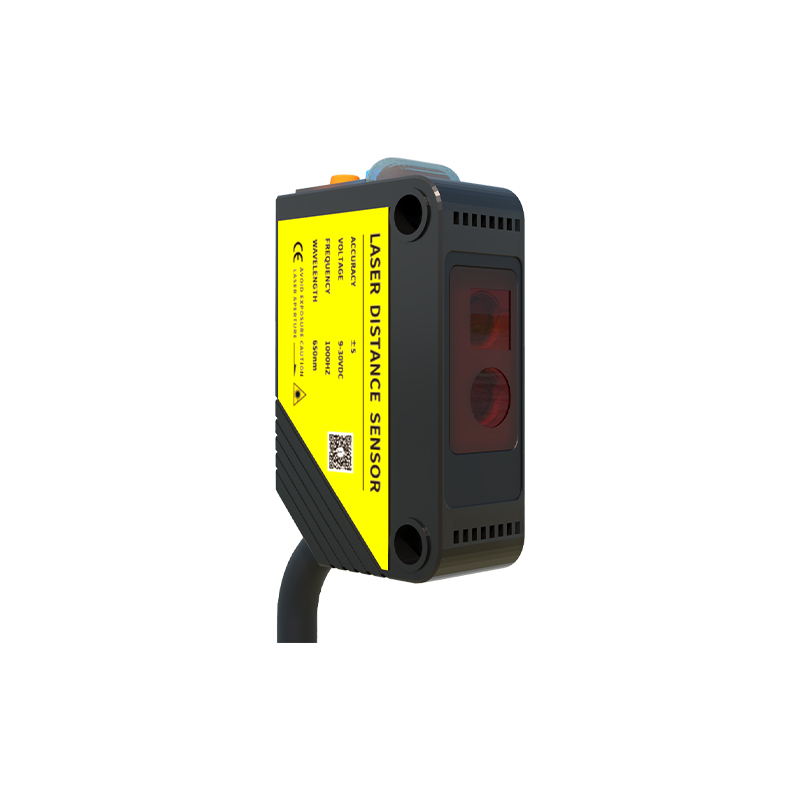
The operating environment is a primary culprit behind sensor instability. Photoelectric sensors, particularly those using visible or infrared light, are highly susceptible to ambient light interference. Strong sunlight, welding arcs, or other high-intensity light sources can saturate the sensor's receiver, causing it to misinterpret signals. Similarly, airborne contaminants like dust, oil mist, steam, or smoke can obstruct or scatter the light beam. Over time, a thin film of grime can accumulate on the sensor's lens or reflector, progressively attenuating the light signal until it becomes unreliable. Regular cleaning schedules using appropriate, non-abrasive materials are essential. For challenging environments, selecting sensors with robust housings (IP67 or higher), specific spectral ranges (e.g., using modulated infrared light to ignore ambient light), or specialized coatings can dramatically improve stability.
Power Supply and Electrical Noise Issues
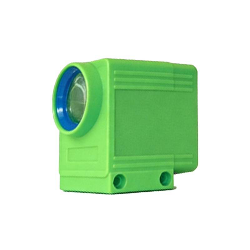
An unstable or noisy power supply is a frequent but often overlooked cause of erratic sensor behavior. Voltage fluctuations, spikes, or sags below the sensor's specified operating range can cause the internal circuitry to reset or behave unpredictably. Furthermore, electrical noise from nearby high-power equipment such as motors, variable frequency drives (VFDs), solenoids, or welding machines can induce transient signals on both power and output lines. This electromagnetic interference (EMI) can be coupled inductively, capacitively, or through common ground paths. To combat this, ensure the sensor is powered by a clean, regulated DC supply. Implementing proper shielding for sensor cables, using twisted-pair wires, installing ferrite cores, and maintaining physical separation from noise sources are critical practices. Proper grounding, following a single-point star grounding scheme, is paramount to drain away unwanted noise currents.
Mechanical Misalignment and Vibration
Photoelectric sensors, especially through-beam and retro-reflective types, require precise optical alignment. Even minor shifts due to machine vibration, thermal expansion, or accidental impacts can misalign the beam, leading to a weak or intermittent signal. In diffuse reflective sensors, the detection reliability heavily depends on the object's surface properties and the consistent positioning of the target within the sensing field. Excessive machine vibration can cause the sensor itself or its mounting bracket to loosen, exacerbating alignment issues. Securely mounting the sensor using vibration-dampening brackets and periodically verifying alignment with an alignment tool or indicator are necessary maintenance steps. For vibrating environments, choosing sensors with a generous alignment tolerance or a background suppression function can enhance performance.
Incompatible Target Characteristics
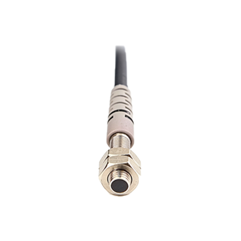
The sensor's performance is intrinsically linked to the properties of the target object. An unstable output may occur if the target's size, color, surface finish, or material is unsuitable for the chosen sensor type. For instance, a shiny, reflective surface can deflect a diffuse sensor's beam unpredictably, while a dark, matte, or translucent object may not reflect enough light back to a diffuse or retro-reflective sensor. Transparent objects, like glass or clear plastic, pose a significant challenge for standard sensors. The solution lies in careful sensor selection during the design phase. For difficult targets, consider using a through-beam sensor (which detects interruption of the beam), a polarized retro-reflective sensor (to ignore shiny surfaces), or a sensor with a focused, precise beam spot and adjustable sensitivity to fine-tune the detection threshold for the specific target.
Sensor Degradation and End-of-Life Factors
Like all electronic components, photoelectric sensors have a finite operational lifespan. The light-emitting diode (LED) at the heart of the sensor gradually loses intensity over tens of thousands of hours. This aging process reduces the signal-to-noise ratio, making the sensor more vulnerable to the interference factors mentioned earlier. Other components, such as capacitors or output transistors, can also degrade over time, especially when operated in high-temperature environments. While not always predictable, a gradual increase in instability can be a sign of sensor aging. Implementing a preventive maintenance program that includes periodic performance checks and scheduled replacement of sensors in critical applications can prevent unexpected failures. Monitoring the sensor's received light intensity, if supported by its diagnostics, provides valuable data on its health.
Configuration and Sensitivity Settings
Improper configuration is a common user-induced cause of instability. Most modern photoelectric sensors feature a sensitivity potentiometer or digital settings. If the sensitivity is set too high, the sensor may detect background objects, dust, or even subtle air movements. If set too low, it may fail to detect a legitimate target or become intermittent as environmental conditions slightly change. The "teach-in" or calibration procedure must be performed under normal operating conditions, with the target present and absent. For sensors with a timer function (on-delay, off-delay, one-shot), incorrect timer settings can create the illusion of an unstable output. Always refer to the manufacturer's manual to configure the sensor correctly for its specific mode of operation (light-on/dark-on) and for the required output logic.
Conclusion and Systematic Troubleshooting Approach
Addressing unstable output in photoelectric sensors requires a systematic approach. Begin by observing the pattern of instability and correlating it with machine cycles or environmental changes. Visually inspect the sensor and lens for contamination, and verify mechanical alignment and mounting. Check the power supply voltage with a multimeter under load. Review the target object's characteristics against the sensor's specifications. Finally, examine the wiring for loose connections, damaged cables, or improper grounding. Isolating the sensor from the control system with a tester can help determine if the issue lies with the sensor or the downstream PLC/controller. By methodically investigating these areas—environment, power, mechanics, target, sensor health, and configuration—engineers can reliably diagnose and resolve the instability, ensuring robust and continuous operation of automated systems.