Understanding the Core Function and Types
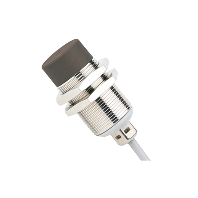
Before putting pen to paper or opening a CAD tool, a clear understanding of the proximity sensor's function is paramount. A proximity sensor detects the presence or absence of an object within its sensing range without physical contact. The schematic must accurately reflect its operational principle. Common types include Inductive Proximity Sensors (for detecting metallic objects), Capacitive Proximity Sensors (for detecting both metallic and non-metallic materials), and Photoelectric Sensors (using light beams). Each type has distinct internal components that the schematic must symbolize correctly. For instance, an inductive sensor's core is a coil and oscillator circuit, while a photoelectric sensor involves an LED and phototransistor.
Selecting and Applying Standard Schematic Symbols
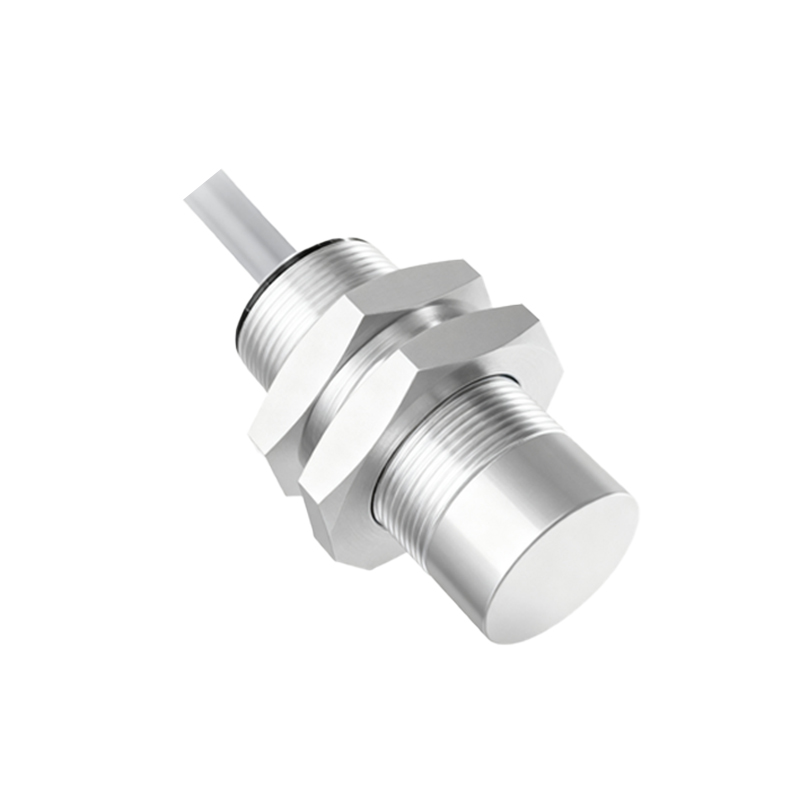
The foundation of a professional schematic is the use of standardized symbols. Proximity sensors are typically represented by a square or diamond shape with specific internal markings. The symbol should clearly indicate the sensor type. For an inductive sensor, the symbol often includes a coil representation. A photoelectric sensor symbol might show a diode for the emitter and a transistor for the receiver. Crucially, the symbol must include connection points, usually numbered. A standard 3-wire DC sensor, for example, will have terminals for Brown (V+), Blue (V- or 0V), and Black (Output). The schematic symbol should label these as +V, COM, and OUT, or use pin numbers (1, 2, 3) with a separate legend.
Defining Power Supply and Ground Connections
A properly drawn schematic leaves no ambiguity about power requirements. Clearly indicate the voltage rating (e.g., 10-30V DC) near the sensor symbol. Draw the power source, such as a 24VDC power supply, and connect its positive terminal to the sensor's V+ pin. Connect the power supply's negative terminal to the sensor's COM pin and, importantly, to the system common ground. This ground connection is vital for the output circuit's return path. Use clear net labels like "+24V" and "GND" to improve readability across multiple schematic sheets. Always include decoupling capacitors near the sensor's power pins if the design requires noise immunity, though this is more common in the sensor's internal design.
Integrating the Output Configuration Circuit
This is the most critical part of the drawing, defining how the sensor interacts with the controller (PLC, relay, microcontroller). Proximity sensors have either a PNP (sourcing) or NPN (sinking) transistor output. The schematic must accurately depict which type is used. For a PNP sensor, the output pin switches the positive voltage. The load (e.g., a PLC input module) is connected between the output pin and ground. For an NPN sensor, the output pin switches the ground path. The load is connected between the positive supply and the output pin. Draw the load (often represented as a resistor or a PLC input symbol) and show its connection explicitly. Misrepresenting this will lead to a non-functional or damaged circuit.
Incorporating Protective and Indicator Elements
A robust schematic includes protective components for reliability. While many modern sensors have built-in protection, it is good practice to show external components if used. This may include a fuse in series with the power line and a Transient Voltage Suppression (TVS) diode across the power terminals to protect against voltage spikes. Furthermore, indicate the connection of the sensor's status LED, if applicable. Often, this LED is internally connected, but showing it on the schematic aids in troubleshooting. For clarity, you can add a note specifying LED color (e.g., "Green - Power ON, Yellow - Object Detected").
Applying Labels, Annotations, and Best Practices
A schematic is a communication tool. Use clear, unique reference designators for each component (e.g., PS1 for Proximity Sensor 1). Add a title block with sensor part number, model, and sensing range. Use wire tags or net names for all connections, especially the output signal (e.g., "PROX1_INPUT"). Annotate the drawing with key specifications: "NPN, NO (Normally Open)", "Sensing Distance: 5mm", "Output Current: 200mA max." Follow a logical flow: power from left to right, signal flow from top to bottom. Ensure there are no dangling connections; every line must have a definitive start and end point. Finally, perform a thorough check to verify that the symbol, wiring, and annotations match the sensor's datasheet exactly.