Introduction to 5-Wire Photoelectric Sensors
In industrial automation, photoelectric sensors are indispensable for detecting the presence, absence, or distance of objects without physical contact. Among various configurations, the 5-wire photoelectric sensor stands out for its versatility and enhanced functionality, typically offering both Normally Open (NO) and Normally Closed (NC) output contacts from a single device. This design provides greater flexibility in control logic design, allowing engineers to tailor the sensor's response to specific application requirements, such as fail-safe operations or complex sequencing. Understanding its wiring is fundamental to ensuring reliable system integration and optimal performance.
Understanding the Wire Color Code and Functions
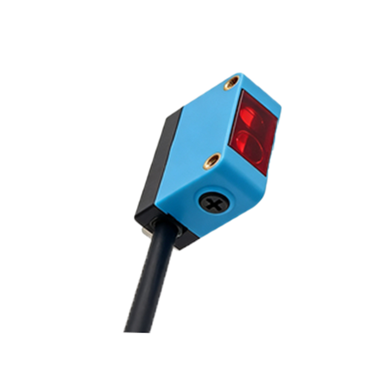
A standard 5-wire DC sensor follows a common color-coding convention, though it is crucial to always verify with the manufacturer's datasheet. The typical configuration is as follows: Brown wire is connected to the positive DC supply voltage (often +12V or +24V DC). Blue wire is connected to the negative DC supply or 0V common (DC ground). Black wire is the output signal for the Normally Open (NO) contact. White wire is the output signal for the Normally Closed (NC) contact. The fifth wire, often Pink or Gray, is used for additional functions. This extra wire is frequently a diagnostic output, a teach-in wire for setting sensitivity, or a control input for switching between light-on/dark-on modes. The specific function of this wire varies significantly between models and brands.
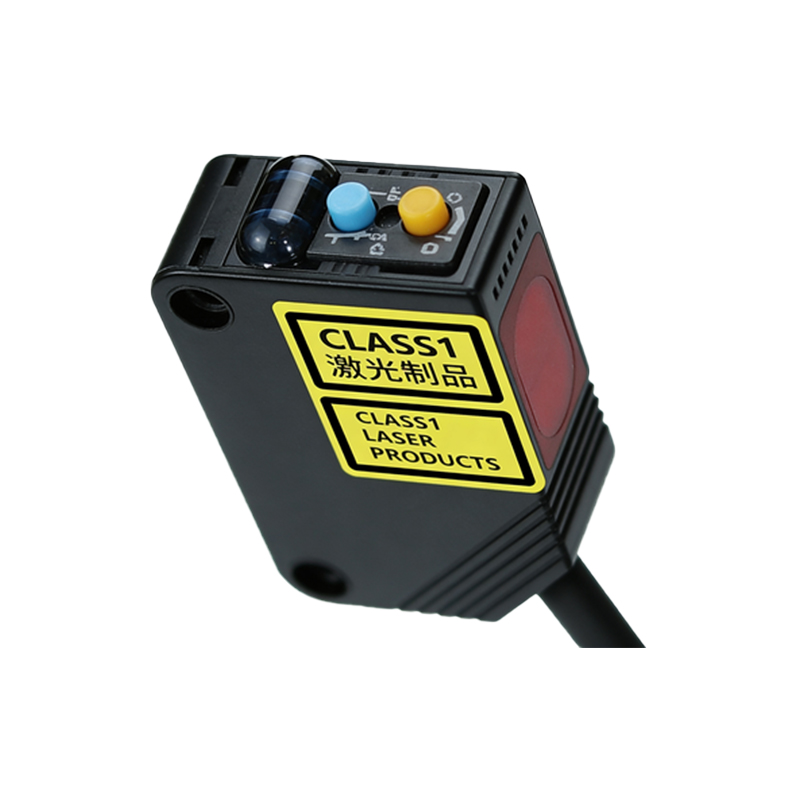
Standard Wiring Diagram and Connection Procedure
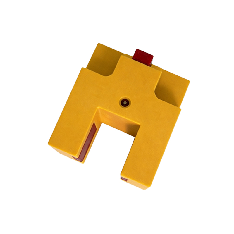
The core of integration lies in the wiring diagram. For a typical NPN output type sensor (sinking), the connection is as follows: Connect the Brown wire to the positive terminal of your DC power supply. Connect the Blue wire to the negative terminal of the same supply. The load (e.g., a PLC input, relay coil, or indicator) for the NO function is connected between the positive supply and the Black wire. When the sensor detects an object, the NPN transistor for the NO circuit activates, connecting the Black wire to the Blue wire (ground), thus completing the circuit and energizing the load. Conversely, for the NC output (White wire), the load is wired between the positive supply and the White wire. In its normal state (no detection), this circuit is closed. Upon detection, the circuit opens, de-energizing the load. The fifth wire (e.g., Pink) must be connected according to its purpose; for a teach-in function, it might be momentarily connected to the positive supply to store a sensing parameter.
Key Considerations for Reliable Installation
Several practical factors ensure long-term reliability. First, always use a stable, regulated DC power supply within the sensor's specified voltage range to prevent erratic behavior. Second, implement proper electrical protection. Installing a fuse in the supply line and using surge suppressors is advisable, especially in environments with inductive loads like motors or solenoids. Third, pay attention to wiring practices. Use shielded cables in electrically noisy environments, grounding the shield at the controller end only to minimize electromagnetic interference (EMI). Keep sensor cables away from high-voltage power lines and motor drives. Finally, consider the load current. Ensure the sensor's maximum switching current is not exceeded by the combined load connected to its outputs.
Troubleshooting Common Wiring Issues
Even with a correct diagram, issues may arise. If the sensor has no power, verify voltage between Brown (+) and Blue (-) wires. If the output does not switch, check the load connection and confirm if you are using the correct output wire (Black for NO, White for NC) for your control logic. Use a multimeter to measure the voltage between the output wire and the Blue wire. It should change state (e.g., from high to low voltage for an NPN NO output) when the sensing condition is met. If the fifth wire is for diagnostics and an alarm LED is active, consult the manual to interpret the fault code, which could indicate misalignment, contamination, or a wiring fault. Always isolate power before making any wiring changes.
Application Examples in Industrial Systems
The dual-output capability of 5-wire sensors makes them ideal for sophisticated tasks. In a packaging machine, the NO output can trigger a filler when a box is present, while the NC output can signal a "fault" or "jam" condition to the main controller if the box is absent at a critical point. In automated storage, a sensor can use its teach-in wire (the fifth wire) to quickly calibrate for different package sizes. Another common use is in safety-interlocked guarding, where the NC output provides a mandatory safety signal that must be uninterrupted for the machine to operate, ensuring a fail-safe design. The flexibility to choose between NO and NC logic within one device saves panel space and simplifies inventory management.
Conclusion and Best Practices
Mastering the wiring of a 5-wire photoelectric sensor is a key skill for control engineers and technicians. The process extends beyond simple connection; it involves understanding the application's logic requirements, selecting the appropriate output type, and implementing robust installation practices. Always prioritize consulting the specific product manual over generic guides, as wire colors and the function of the fifth wire can differ. By following the correct wiring diagram, employing sound electrical practices, and leveraging the sensor's dual-output flexibility, you can build more reliable, efficient, and maintainable automation systems.