Understanding the Basics of 3-Wire Proximity Sensors
A 3-wire proximity sensor is a fundamental component in industrial automation, commonly used for non-contact detection of metallic objects. Unlike 2-wire sensors that are wired in series with the load, 3-wire sensors provide a dedicated power supply, ground, and output signal wire. This design offers superior performance, faster switching speeds, and better noise immunity. The three wires are typically color-coded: brown for positive DC supply voltage (often +24V DC), blue for the common ground or negative supply, and black for the switched output signal. Understanding this configuration is the critical first step before attempting any diagnostic procedure like short-circuiting for testing purposes. The output can be either NPN (sinking) or PNP (sourcing), which determines how the load is connected in relation to the supply voltage. This distinction is paramount for correct and safe short-circuit testing.
Purpose and Precautions for Short-Circuit Testing
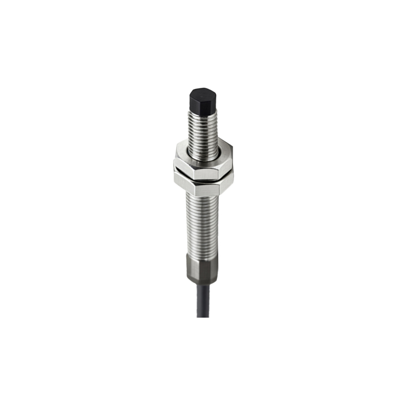
Short-circuiting a sensor is not a standard operational procedure but a diagnostic technique used primarily for troubleshooting. Engineers may perform this test to isolate faults within a control system. For instance, by manually creating the sensor's output state, one can determine if a malfunction lies within the sensor itself, the wiring, or the downstream controller (like a PLC). It is a method to bypass the sensor to verify the integrity of the rest of the circuit. Extreme caution must be exercised. Always disconnect power from the circuit before making any connections. Use appropriate personal protective equipment (PPE) and insulated tools. Confirm the sensor's specifications, particularly its voltage rating and output type, from the manufacturer's datasheet. Incorrect shorting can cause permanent damage to the sensor, the power supply, or connected programmable logic controllers.
Step-by-Step Procedure for Shorting a PNP Sensor
A PNP (sourcing) proximity sensor provides a positive voltage on its output wire (black) when activated. To simulate an "ON" state for testing, you essentially need to connect the output wire directly to the positive supply. First, ensure the system is powered down. Identify the three wires: brown (+V), blue (0V/GND), and black (output). For a basic functionality test of the downstream circuit, you can create a temporary short. Using a fused jumper wire or a test lead, carefully connect the black (output) wire to the brown (+V) wire at the sensor's connection point or at the terminal block. This connection simulates the sensor detecting an object, allowing current to flow from the sensor's output to the load. After securing the connection, re-apply power to the system. The load (e.g., a PLC input, relay, or indicator lamp) should activate, confirming that the circuit path from the sensor output onward is functional. Remember to remove the jumper and restore original wiring after testing.
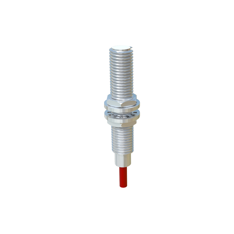
Step-by-Step Procedure for Shorting an NPN Sensor
An NPN (sinking) sensor operates differently. When activated, it connects the output wire (black) to the ground or negative supply (blue). To simulate its "ON" state, you must connect the output wire to the common ground. With power disconnected, locate the blue (0V/GND) and black (output) wires. To test the downstream circuit, use a jumper wire to connect the black wire to the blue wire. This action closes the circuit to ground, mimicking the sensor's switching behavior. Once the connection is secure, restore power. In a typical NPN circuit, the load is connected between the positive supply (+V) and the sensor's output. Therefore, shorting the output to ground completes the circuit, allowing current to flow through the load and activate it. Observing this activation verifies the health of the wiring and the load. It is crucial to note that shorting the black output wire of an NPN sensor to the brown (+V) wire would create a direct short circuit across the power supply, likely tripping a fuse or causing damage.
Interpreting Results and Common Troubleshooting Scenarios
The outcome of the short-circuit test provides clear diagnostic direction. If the load activates normally when the sensor is manually shorted, it confirms that the power supply, wiring, and the load itself are operational. The fault likely resides in the proximity sensor (e.g., damaged sensing element, misalignment, or incorrect sensing distance). If the load fails to activate even with a proper short, the problem exists elsewhere. Investigate the power supply for correct voltage, check for blown fuses, inspect all wiring for breaks or loose connections, and verify the load device (PLC input