Introduction to Photoelectric Sensor Experiment Box
A photoelectric sensor experiment box is an essential educational and prototyping tool for engineers, technicians, and students in automation and industrial electronics. This compact system typically integrates various types of photoelectric sensors—such as through-beam, retro-reflective, and diffuse reflective models—alongside necessary power supplies, signal indicators, and terminal blocks. The primary purpose is to provide a hands-on platform for understanding sensor operation, characteristics, and integration into control circuits. By working with a physical wiring setup, users gain practical insights into real-world applications, from object detection on conveyor belts to precise positioning in assembly lines. The experiment box demystifies the theoretical principles of light emission, reception, and signal conditioning, bridging the gap between textbook knowledge and industrial practice.
Components and Terminal Identification
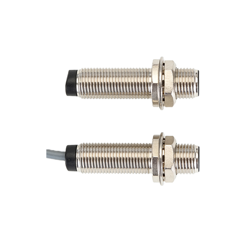
Before examining the wiring diagram, it is crucial to identify the key components within a standard experiment box. Common elements include a DC power input terminal (often 12-24V DC), a ground terminal, and output terminals for each sensor type. Each photoelectric sensor unit will have at least three connection points: V+ (power supply positive), V- (power supply negative or ground), and OUT (switched output signal). Many boxes also feature a teach-in button or sensitivity adjustment potentiometer for configuring sensing ranges. Additionally, you may find LED indicators for power and output status, relay modules for switching higher loads, and possibly a programmable logic controller (PLC) interface module. Clearly labeling these terminals according to the manufacturer's datasheet is the first step to successful wiring.
Standard Wiring Diagram Overview
The core wiring diagram illustrates how to interconnect the power source, sensors, and output devices. A typical setup begins with connecting a regulated DC power supply—for instance, 24V DC—to the experiment box's main power input terminals. The positive lead from the supply attaches to the V+ rail, and the negative lead to the V- or COM rail. Each individual sensor then draws power from these common rails: its V+ pin connects to the V+ rail, and its V- pin to the V- rail. The sensor's OUT pin is routed to the load device, which could be an indicator LED, a relay coil, or a PLC input module. It is vital to include a current-limiting resistor if driving an LED directly. The diagram should clearly show these paths, using distinct line styles or colors for power and signal lines to enhance readability.
Step-by-Step Wiring Procedure
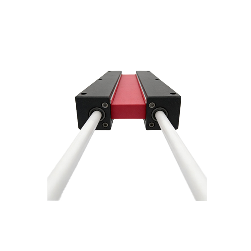
Begin by ensuring all power is disconnected. First, secure the DC power supply wires to the experiment box's main input terminals, observing correct polarity. Next, for a through-beam sensor pair, wire the emitter unit: connect its V+ and V- to the power rails. For the separate receiver unit, similarly connect V+ and V- to the same rails. Then, run a wire from the receiver's OUT terminal to the positive side of your load (e.g., a buzzer or lamp). Connect the other side of the load back to the V- rail to complete the circuit. For retro-reflective or diffuse sensors, which house emitter and receiver in one housing, follow the same three-wire pattern: power the sensor and connect its output to the load. Always double-check connections against the diagram before applying power to prevent short circuits or damage.
Configuration and Testing Methods
After wiring, configuration and testing validate the setup. Many photoelectric sensors on experiment boxes feature adjustable sensing ranges. Use a small screwdriver to turn the potentiometer while observing the output indicator LED. Place a target object (like a white card) within the specified sensing distance; the output LED should illuminate when the object is detected. For a quantitative test, connect a multimeter in voltage mode between the sensor's OUT terminal and V- to measure the output signal change. In a teaching mode, some sensors allow you to set the sensitivity by pressing a button when the target is at the desired detection point. Document the response time and sensing range under different lighting conditions to fully characterize the sensor's performance.
Common Applications and Circuit Variations
The experiment box enables exploration of diverse applications. A basic object detection circuit can be expanded into a counting system by connecting the sensor output to a counter module. For bidirectional sensing, two sensors can be wired to a logic gate (AND/OR) to determine object direction. In safety interlock designs, the sensor output may connect to a relay that cuts power to a motor when a guard door is open. Another variation involves connecting the sensor output to the input of a small PLC, then programming the PLC to control an actuator. These practical circuits illustrate how photoelectric sensors serve as the eyes of automated systems, providing critical input for decision-making in control logic.
Troubleshooting Wiring Issues
If the sensor fails to operate after wiring, follow a systematic troubleshooting approach. First, verify power supply voltage at the experiment box terminals with a multimeter. Check that all connections are tight and correctly placed according to the diagram. Inspect the sensor's LED indicators: a steady power LED indicates good voltage supply, while a blinking output LED may signal misalignment or inadequate reflectance. Ensure the sensing object is within range and suitable for the sensor type (e.g., retro-reflective sensors require a reflector). If the output does not switch, test by temporarily connecting the load directly to power to rule out load failure. Consult the sensor datasheet for specific error codes or indicator patterns that aid diagnosis.
Safety Precautions and Best Practices
Always adhere to electrical safety standards when using the experiment box. Use only the recommended DC voltage to prevent overheating or component failure. Ensure all wire insulation is intact and terminals are not loose to avoid accidental shorts. When connecting to external devices like PLCs or relays, confirm their voltage compatibility. Implement proper grounding if the experiment box chassis is metal. As a best practice, draw your own wiring diagram before starting, label all wires, and keep a log of configurations and test results. Regularly inspect the box for wear or damage. These habits not only ensure safe operation but also reinforce professional engineering discipline, which is invaluable in real industrial environments.