Introduction to Photoelectric Sensor Symbols
In the realm of industrial automation and electrical control system design, the ability to accurately interpret and utilize schematic symbols is paramount. Photoelectric sensors, ubiquitous in applications ranging from object detection and counting to level control and safety systems, are represented by a standardized set of electrical symbols. These symbols form the graphical language that allows engineers, technicians, and designers across the globe to communicate complex circuit functionality quickly and unambiguously. Understanding these symbols is not merely an academic exercise; it is a fundamental skill for creating, troubleshooting, and maintaining efficient and reliable automated systems. This guide delves into the standard electrical symbols for photoelectric sensors, explaining their components, variations, and practical application in circuit diagrams.
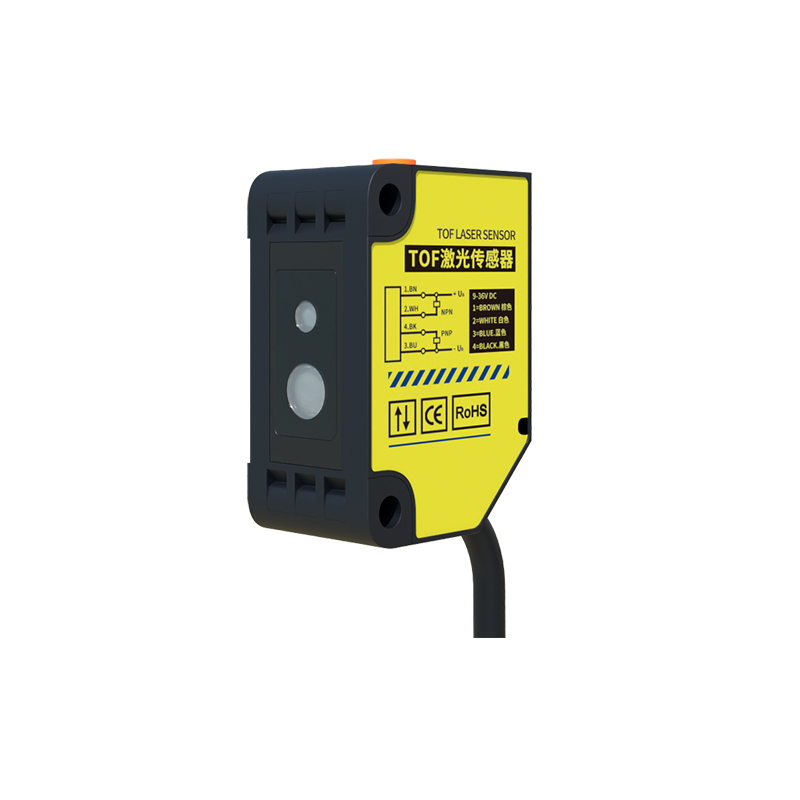
Core Components of the Symbol
The fundamental electrical symbol for a photoelectric sensor is derived from the basic symbol for a light source and a light-sensitive receiver. At its core, it consists of two primary elements enclosed within a circle or a rectangle, representing the device's housing. The transmitter side is typically denoted by a simple diode symbol (a triangle pointing away from a line) with two arrows emanating outward, signifying the emission of light rays. The receiver side is represented by a photodiode or phototransistor symbol, which resembles a standard diode but with two arrows pointing inward, indicating the reception of light. These two components are often shown separated, connected by a dashed or dotted line symbolizing the light beam path. This clear visual separation is crucial for understanding the sensor's operating principle in through-beam, retro-reflective, and diffuse reflective modes.
Symbol Variations for Different Operating Modes
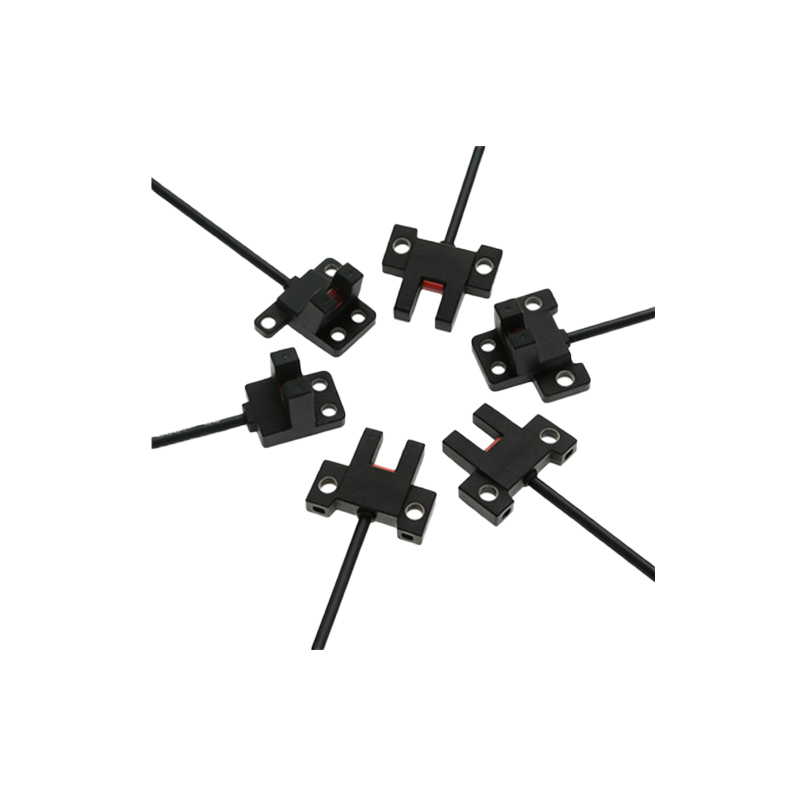
Standardization bodies like the International Electrotechnical Commission (IEC) and the National Electrical Manufacturers Association (NEMA) define specific symbol variations to distinguish between the primary operating types. For a through-beam sensor, the symbol explicitly shows the transmitter and receiver as two distinct, separate blocks, often with the part number or label split (e.g., BOS-1 and BOS-2). The light beam line connects them. The retro-reflective sensor symbol combines the emitter and receiver into a single block or circle, with the light beam line ending in a small perpendicular bar or a diamond shape, representing the reflector. A diffuse reflective sensor (proximity mode) uses a similar combined symbol, but the light beam line typically curves back to the housing itself, illustrating that the sensor detects light reflected directly from the target object. These subtle graphical differences are essential for accurate diagram interpretation.
Electrical Connection Points and Output Types
Beyond the optical symbol, the electrical connections are critically important. The symbol will include connection points, usually represented by small lines protruding from the housing. These are labeled according to function: power supply positive (V+ or +V), power supply negative (V- or 0V), and the output signal line. The output type is indicated by the internal switching symbol. A load switching device, such as a transistor, is shown inside the housing. For a PNP (sourcing) output, the switch connects the output line to the positive supply. An NPN (sinking) output symbol shows the switch connecting the output to the negative supply. Some symbols also incorporate the output state notation, like "dark-on" (operates when beam is blocked) or "light-on" (operates when beam is received), which may be noted textually near the symbol.
Incorporation into Ladder Logic Diagrams
In programmable logic controller (PLC) systems, photoelectric sensors are integral inputs. Their representation in ladder logic (or ladder diagrams) differs from the detailed component symbol. Here, the sensor is represented simply by a standard contact symbol (normally open or normally closed) labeled with a unique address (e.g., I0.1). The choice of a normally open (NO) or normally closed (NC) contact symbol is determined by the sensor's "light-on" or "dark-on" configuration and the desired logic in the control program. The detailed electrical symbol with its power connections is typically found in the separate power distribution or terminal diagram, while the ladder logic focuses purely on the control function. This separation of concerns is a key principle in professional electrical documentation.
Practical Application and Diagram Best Practices
When creating or reading electrical drawings, consistency is key. Always refer to the legend or symbol list provided with the drawing set. It is considered best practice to place the sensor symbol near the physical location it represents in a machine layout diagram and to clearly label it with a unique tag, such as "PE101" for Photoelectric Sensor #101. This tag should cross-reference to the parts list, specification sheet, and terminal designations. Wiring paths should be drawn clearly, and for complex systems, the use of different line styles or colors for AC power, DC power, and signal lines can greatly enhance readability. Remember, a well-drawn diagram using precise photoelectric sensor symbols minimizes commissioning time and reduces the potential for costly wiring errors.
Conclusion and Symbol Evolution
Mastering the electrical symbols for photoelectric sensors is a critical competency for any professional involved in control system design. These symbols provide a concise, universal method to convey the sensor's technology, operating mode, output configuration, and wiring requirements. As sensor technology advances, incorporating features like IO-Link, analog outputs, or advanced diagnostics, the basic symbolic representation may be augmented with additional notations or new standard symbols may emerge. However, the foundational principles outlined here will remain constant. By diligently applying this symbolic language, engineers ensure clarity, promote safety, and facilitate efficient collaboration throughout the lifecycle of an automation project.