Understanding Photoelectric Sensor Fundamentals
Photoelectric sensors are indispensable components in modern industrial automation, particularly on conveyor systems. They operate by emitting a light beam—typically infrared, visible red, or laser—and detecting changes in the received light signal. The three primary sensing modes are through-beam, retro-reflective, and diffuse reflective. Through-beam sensors offer the longest sensing range and highest reliability, as they consist of separate emitter and receiver units. Retro-reflective models use a single housing with a built-in reflector, while diffuse sensors detect light reflected directly from the target object. Selecting the correct sensing mode is the foundational step before any installation process begins, as it directly impacts alignment complexity and environmental robustness.
Pre-Installation Planning and Site Assessment
A successful installation begins long before mounting the sensor. Conduct a thorough assessment of the conveyor line environment. Identify potential sources of interference such as ambient light (sunlight or high-intensity factory lighting), dust, steam, oil mist, or vibration. Determine the required sensing distance, which must account for the size, color, and surface texture of the target objects. For instance, detecting a glossy, reflective package requires a different sensor type and setup than detecting a matte black object. Also, verify the electrical specifications—ensuring the sensor's voltage (commonly 12-24V DC or 100-240V AC) and output type (PNP/NPN, relay) are compatible with the conveyor's control system, such as the PLC.
Mechanical Mounting and Physical Alignment
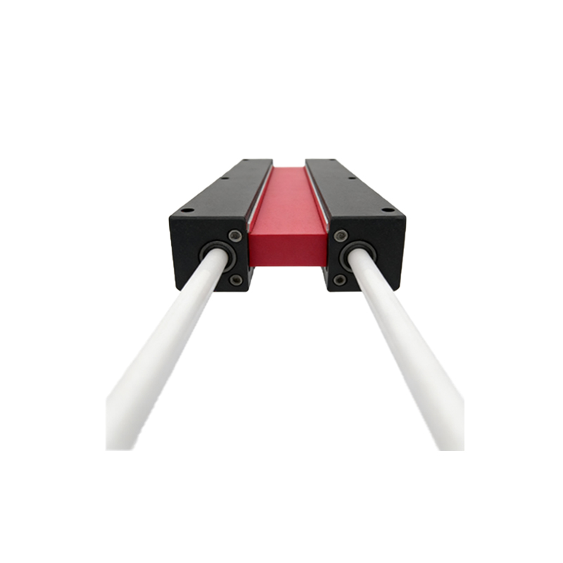
Secure and stable mounting is critical. Use the provided brackets or rugged mounting accessories to fix the sensor firmly to the conveyor frame. Avoid locations with excessive mechanical shock or vibration. For through-beam sensors, first mount the emitter and receiver units on opposite sides of the conveyor. Use alignment tools if provided. The key is to achieve perfect optical axis alignment. Even a slight misalignment can cause unreliable operation or complete failure. For retro-reflective sensors, ensure the reflector is mounted perpendicular to the sensor's beam and that the background is free of highly reflective surfaces that could cause false triggers. Allow for minor adjustments in all axes during mounting to facilitate fine-tuning.
Electrical Wiring and Connection Protocols
Follow the manufacturer's wiring diagram meticulously. Always disconnect power before making connections. Use shielded cables for the sensor's power and signal lines, especially in environments with electromagnetic noise from motors or variable frequency drives. Ground the shield at the control panel end only to prevent ground loops. Connect the sensor's output to the designated input module of the PLC or control relay. Pay close attention to the sink (NPN) or source (PNP) configuration to match your system. Implement proper circuit protection, such as fuses or surge protectors, particularly for sensors in long cable runs or harsh environments. Neatly route and secure all cables in cable ducts or conduits to prevent damage from moving conveyor parts.
Configuration, Calibration, and Sensitivity Adjustment
After powering up, configure the sensor's operating parameters. Many modern sensors feature teach-in functions or potentiometers for setting sensitivity and response time. Adjust the sensitivity so the sensor reliably detects the target object while ignoring background or passing objects on adjacent conveyor lanes. Set an appropriate response time—fast enough for high-speed lines but not so fast that it becomes susceptible to electrical noise. For challenging applications with translucent objects or varying object colors, consider using sensors with background suppression or true color detection technology. Perform calibration with the actual target objects under normal operating conditions, not just during a static test.
System Integration and Functional Testing
Integration with the conveyor control logic is the next crucial phase. Program the PLC to interpret the sensor's signal correctly. This may involve creating logic for object counting, jam detection, positioning for robotic pick-and-place, or triggering diverters. Conduct comprehensive functional tests. Run the conveyor at its maximum operational speed and feed a representative sample of products, including edge-case items (e.g., smallest, largest, darkest, lightest). Verify that the sensor triggers consistently without false positives or missed detections. Test under different lighting conditions that may occur throughout a working day.
Ongoing Maintenance and Troubleshooting Practices
Regular maintenance ensures long-term reliability. Establish a schedule to clean the sensor's lens and the reflector (if used) to prevent buildup of dust, grime, or condensation that attenuates the light beam. Periodically check mounting hardware for loosening due to vibration. Monitor the sensor's performance indicators, such as a stability LED if available. Common troubleshooting steps include verifying power supply, checking for loose connections, re-aligning the optical path, and re-adjusting sensitivity. Keep a log of any issues and their resolutions to build a knowledge base for future maintenance. Consider implementing predictive maintenance by monitoring signal strength trends over time.
Advanced Considerations for Complex Applications
For highly demanding applications, explore advanced sensor features. In high-speed sorting lines, sensors with extremely fast response times (microseconds) are necessary. For precise positioning, laser-based sensors with fine spot sizes offer high accuracy. In environments with heavy contamination, sensors with automatic lens cleaning systems or high IP ratings (IP67/IP69K) are essential. For networked systems, IO-Link enabled photoelectric sensors provide valuable diagnostic data, parameterization capabilities, and easier integration into Industry 4.0 architectures, enabling remote monitoring and configuration changes without physical access to the sensor on the conveyor line.