Understanding Photoelectric Sensor Components
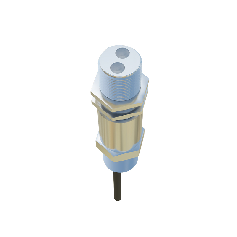
Before beginning any disassembly or installation procedure, it is crucial to understand the fundamental components of a standard photoelectric sensor. A typical unit consists of a housing, the emitter (light source), the receiver (phototransistor or photodiode), the lens assembly, electrical connection terminals, and often an alignment indicator. The housing protects the internal electronics from environmental factors such as dust, moisture, and mechanical impact. The emitter generates a modulated light beam, usually infrared, visible red, or laser, which is projected towards the target area. The receiver detects the presence or absence of this light beam, and its output signal changes state accordingly. Familiarizing yourself with these parts by reviewing the manufacturer's datasheet and diagrams is the first step to a safe and correct procedure.
Essential Tools and Safety Precautions
Gather all necessary tools and personal protective equipment (PPE) before starting. Required tools typically include a set of precision screwdrivers (flathead and Phillips), hex keys (Allen wrenches), needle-nose pliers, a multimeter for continuity and voltage testing, and a clean, static-free work surface. For installation, you may also need mounting brackets, conduit fittings, and appropriate wiring tools. Safety is paramount. Always disconnect and lock out all power sources to the sensor and the connected machinery. Verify the absence of voltage using the multimeter. Wear safety glasses to protect your eyes from potential debris and anti-static wrist straps to prevent damage to sensitive electronic components from electrostatic discharge (ESD).
Step-by-Step Disassembly Procedure
The disassembly process is generally performed for maintenance, cleaning, or troubleshooting. Follow these steps meticulously. First, after ensuring power is disconnected, detach the electrical wiring from the sensor's terminal block. Carefully note or photograph the wire connections for correct reassembly. Next, remove the sensor from its mounting bracket by loosening the mounting screws or unlocking the quick-disconnect mechanism. Place the sensor on your work surface. Using the appropriate screwdriver, remove the screws securing the two halves of the sensor housing. Gently separate the housing. Inside, you will see the printed circuit board (PCB). The emitter and receiver are usually soldered onto this board. Do not attempt to remove them unless necessary. For lens cleaning, the lens cap or window can often be unscrewed separately. Avoid touching optical surfaces with your fingers.
Cleaning and Inspection Guidelines
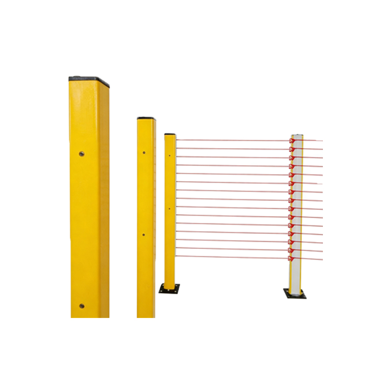
Once disassembled, perform a thorough inspection. Check the lens for any scratches, cracks, or accumulation of dirt, oil, or dust. Clean the lens using a soft, lint-free cloth slightly moistened with isopropyl alcohol. Do not use abrasive materials or harsh chemicals. Inspect the housing seals (O-rings) for any signs of wear, cracking, or deformation, as these are critical for the sensor's ingress protection (IP) rating. Examine the PCB for any visible damage, such as burnt components, cracked solder joints, or corrosion on the terminals. Use compressed air to blow away any loose dust from the internal cavity. This is also an opportune time to check the alignment of the emitter and receiver if they are separate units within the housing.
Reassembly and Functional Testing
Reassembly is essentially the reverse of disassembly. Ensure all components are completely dry and free of contaminants. If the housing seal was removed, reinstall it carefully into its groove. Place the PCB back into the lower housing half, ensuring it sits flat and any alignment pins or tabs are engaged. Carefully mate the upper housing half, making sure no wires are pinched. Reinstall and tighten the housing screws evenly in a cross pattern to avoid warping. Do not over-tighten. Before re-mounting the sensor, perform a basic functional test. Reconnect the wiring temporarily in a safe, bench-top setup if possible. Restore power briefly and observe the sensor's indicator LED. Use a non-reflective test object to interrupt the beam; the output indicator should change state. Verify the output signal with your multimeter.
Installation and Mounting Best Practices
Proper installation is critical for reliable operation. First, select the optimal mounting location. Consider the sensing range, target material, environmental conditions (ambient light, temperature, vibrations), and accessibility for maintenance. Securely attach the mounting bracket to the machine frame using suitable hardware. Mount the sensor onto the bracket, but do not fully tighten the adjustment screws yet. For through-beam sensors, roughly align the emitter and receiver units. For retro-reflective or diffuse sensors, point the sensor towards the intended detection point. Connect the electrical wiring according to the wiring diagram—typically involving power supply (Vcc), ground (GND), and output signal wires. Ensure wires are properly secured in cable glands or conduits to maintain the IP rating.
Precise Alignment and Configuration
Alignment is the most critical step for through-beam and retro-reflective sensors. Many sensors feature a built-in alignment aid, such as a signal strength LED. Slowly adjust the sensor's position while observing this indicator. For through-beam types, align until the receiver indicates maximum received light (often a solid green light). For diffuse sensors, adjust the sensing distance and angle to reliably detect the target while ignoring the background. Once optimal alignment is achieved, securely tighten all mounting and locking screws to prevent shifting from vibration. Finally, configure any adjustable parameters such as sensitivity potentiometers, response time, or light/dark operation mode according to your application requirements. Always refer to the specific sensor's manual for detailed configuration instructions.
Troubleshooting Common Post-Installation Issues
Even after careful installation, issues may arise. If the sensor fails to detect, first verify power and wiring connections. Check for obstructions in the light path or excessive accumulation on the lens. For through-beam sensors, ensure the emitter and receiver are still perfectly aligned. For diffuse sensors, the sensitivity may need fine-tuning if the target's reflectivity is low. Environmental light interference can cause false triggers; consider using a sensor with modulated light or installing a shade. If the output is unstable, investigate potential sources of electrical noise and ensure proper grounding and shielding of cables. Systematic troubleshooting, starting from power and moving to signal path, will typically identify and resolve the problem efficiently.