Understanding Proximity Sensor Fundamentals
Proximity sensors are critical components in industrial automation, designed to detect the presence or absence of objects without physical contact. These sensors operate based on various principles, including inductive, capacitive, ultrasonic, and photoelectric technologies. Inductive sensors detect metallic objects, capacitive sensors respond to both metallic and non-metallic materials, ultrasonic sensors use sound waves for detection, and photoelectric sensors rely on light beams. Each type has specific applications and requires distinct calibration approaches. Before initiating any debugging process, it is essential to verify the sensor model, datasheet specifications, and intended operating environment. Proper understanding of the sensor's sensing range, output type (e.g., NPN, PNP, analog, or digital), and electrical requirements ensures a systematic troubleshooting workflow.
Pre-Calibration Safety and Preparation
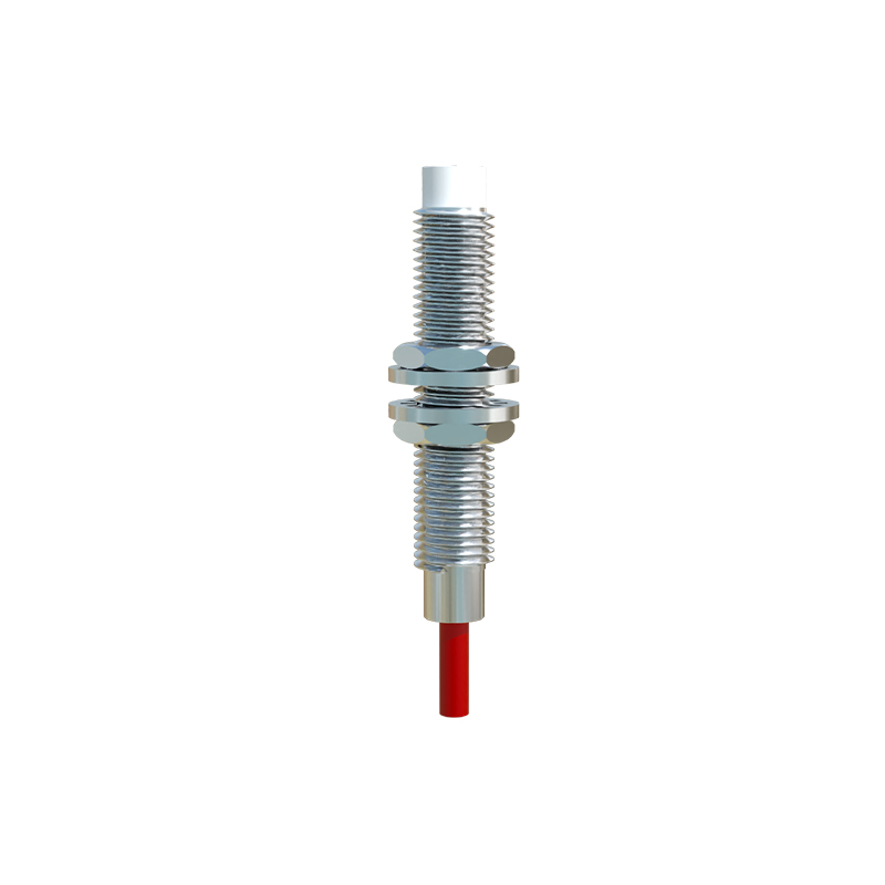
Safety is paramount when working with industrial sensors. Always disconnect power to the control system and sensor circuit before handling or wiring. Use appropriate personal protective equipment (PPE) such as insulated gloves and safety glasses. Verify that the work area is free from flammable materials and ensure proper lockout-tagout (LOTO) procedures are followed. Gather necessary tools: a multimeter for voltage and current measurements, oscilloscope for signal analysis, calibration targets (standardized test objects), and the sensor manufacturer's manual. Check the sensor and cable for physical damage, corrosion, or loose connections. Confirm that the power supply matches the sensor's rated voltage (commonly 12-24V DC) and that the load (e.g., PLC input, relay) is compatible with the sensor's output characteristics.
Wiring Verification and Electrical Testing
Incorrect wiring is a frequent cause of sensor malfunction. For a three-wire DC sensor, typically, the brown wire connects to positive voltage, blue to negative or ground, and black (or white) is the output signal line. Use a multimeter to measure voltage between positive and negative terminals to ensure it is within the specified range. Check for short circuits or ground faults by measuring resistance between wires. If the sensor has an LED indicator, observe its behavior—steady on, flashing, or off—to diagnose issues. For analog sensors, measure the output signal with no target present and with a target at the calibrated distance, comparing values to datasheet expectations. Ensure that the load impedance does not exceed the sensor's maximum rating to avoid output degradation or failure.
Calibration Procedure Step by Step
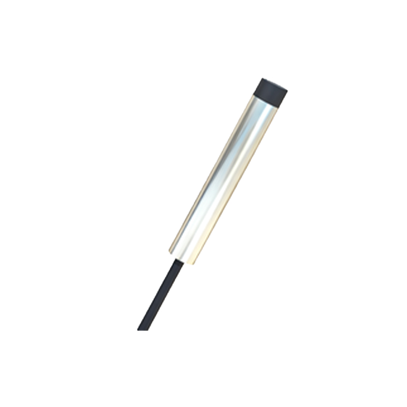
Calibration aligns the sensor's detection parameters with application requirements. Begin by mounting the sensor securely on a stable fixture, ensuring it is aligned perpendicular to the target's approach path. For adjustable sensors, locate the calibration potentiometer or teach-in button. Place the standard target (specified material and size) at the nominal sensing distance. Adjust the sensitivity or threshold setting until the output activates reliably. For sensors with hysteresis adjustment, set the release point to prevent chattering. Use an oscilloscope to monitor response time and signal stability if high-speed operation is needed. Record the calibrated settings and test with multiple targets to ensure consistency. For programmable sensors, follow the manufacturer's software guidelines to set parameters like output delay, window mode, or temperature compensation.
Debugging Common Operational Issues
When a proximity sensor fails to operate correctly, methodical debugging is essential. If there is no output signal, verify power supply integrity and wiring polarity. Check for electromagnetic interference (EMI) from nearby motors or cables, which can be mitigated by shielding or separating signal lines. False triggering may occur due to environmental factors like dust, moisture, or temperature extremes; consider using sensors with appropriate IP ratings or environmental seals. For reduced sensing range, inspect the sensor face for contamination and clean it with a soft cloth. Test with different target materials and sizes, as variations can affect detection capabilities. If the sensor overheats, ensure it is not overloaded or operating above its rated voltage. Consult error codes in the manual for digital sensors with self-diagnostic features.
Advanced Diagnostics and Performance Optimization
For complex systems, advanced diagnostic tools enhance troubleshooting. Use an industrial network analyzer (for IO-Link or fieldbus sensors) to monitor real-time data, such as switching frequency, temperature, and signal quality. Perform a frequency response test to determine the maximum detectable object speed. Analyze temperature drift by operating the sensor across its specified temperature range and recalibrating if necessary. Implement predictive maintenance by logging sensor performance metrics over time to anticipate failures. Optimize sensor placement by considering reflective surfaces, background materials, and multiple sensor interference. For analog sensors, linearity and repeatability tests ensure measurement accuracy. Firmware updates from the manufacturer can resolve known issues or add