Fundamental Principles of Optical Sensing
Optical sensors, primarily photodiodes and phototransistors, operate by converting incident light into an electrical current. This phenomenon, known as the photoelectric effect, is the cornerstone of optical control systems. When photons with sufficient energy strike the semiconductor material within the sensor, they generate electron-hole pairs. This generation creates a measurable photocurrent that is directly proportional to the light intensity. For controlling a diode, typically a Light-Emitting Diode (LED) or a power diode in a circuit, this photocurrent serves as the precise input signal. The key parameters include responsivity, which defines the current output per unit of optical power, and response time, determining how quickly the sensor reacts to changes in light. Understanding these fundamentals is essential for designing effective optical control interfaces, where the sensor's output directly modulates the state or brightness of the target diode.
Core Circuit Configurations for Diode Control
The most straightforward circuit for optical sensor control involves connecting a phototransistor in series with the controlled diode and a current-limiting resistor. In this configuration, the phototransistor acts as a light-dependent switch. Under sufficient illumination, the phototransistor saturates, allowing current to flow through the main circuit path and activating the diode. For more precise control, such as analog dimming of an LED, operational amplifiers (op-amps) are integrated. The photocurrent from a photodiode is fed into a transimpedance amplifier (TIA), which converts the current into a stable voltage signal. This voltage can then be compared against a reference using a comparator circuit to toggle a power MOSFET, which in turn drives the high-power diode. Another advanced configuration utilizes opto-isolators, where an internal LED and phototransistor are coupled. This provides complete electrical isolation between the low-voltage sensor side and the high-voltage/power diode circuit, a critical feature in industrial environments to prevent noise and voltage spikes from interfering with control signals.
Signal Conditioning and Noise Mitigation
Raw signals from optical sensors are often weak and susceptible to various forms of interference, including ambient light fluctuations and electromagnetic noise. Effective signal conditioning is therefore paramount. A primary technique is the use of modulated light sources and synchronous detection. Instead of relying on steady light, the control system uses an LED emitter pulsed at a specific frequency. The photodetector circuit is tuned to respond only to this frequency, effectively filtering out constant ambient light and low-frequency noise. Furthermore, incorporating passive RC (Resistor-Capacitor) low-pass filters at the output of the sensor can smooth out rapid, unwanted signal variations. For digital control systems, the analog photocurrent signal is digitized using an Analog-to-Digital Converter (ADC). Microcontrollers can then implement sophisticated software filters, such as moving average or median filters, to process the digital readings before sending a control command to the diode driver circuit. This layered approach to signal integrity ensures reliable and repeatable diode control.
Industrial Application Scenarios
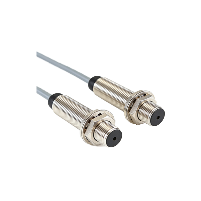
In industrial automation, optical sensor-controlled diodes are ubiquitous. One primary application is in precision object detection and part counting on conveyor belts. A through-beam sensor, with an emitter and receiver on opposite sides, detects the presence of an object breaking the beam. The receiver's photodiode output directly controls an indicator LED on a control panel and can also trigger a solenoid valve or a sorting mechanism via a relay interface. Another critical use is in safety interlock systems. Safety light curtains, consisting of arrays of optical sensors, protect hazardous machine areas. If the beam is interrupted, the sensor output changes state, immediately cutting power to the machine by de-energizing a control relay (often driven by a power diode circuit), thereby preventing accidents. Additionally, in environmental monitoring, photodiodes measure ambient light levels to automatically control street lighting LEDs, optimizing energy consumption based on real-time daylight conditions.
Design Considerations and Best Practices
Successful implementation requires careful attention to several design factors. First, sensor selection must match the spectral response to the light source wavelength; an infrared sensor must be paired with an IR emitter. Second, the operating environment dictates the housing—dusty or wet conditions require sensors with high Ingress Protection (IP) ratings. Thermal stability is another concern, as the dark current of photodiodes increases with temperature, potentially leading to false triggers. Temperature compensation circuits or selecting sensors with low temperature coefficients are common solutions. For driving high-current diodes or LED arrays, the interface circuit must include adequate heat sinking for the driving transistor or MOSFET. Finally, adherence to electromagnetic compatibility (EMC) standards is non-negotiable in industrial settings. Proper board layout, shielding of sensitive signal lines, and the use of ferrite beads can prevent the optical control system from being a source of or victim to electromagnetic interference.