Introduction to 3-Wire Photoelectric Sensors
Photoelectric sensors are pivotal components in industrial automation, detecting the presence, absence, or distance of objects using light beams. Among various configurations, the 3-wire sensor is one of the most common and versatile types. It typically includes three distinct wires: one for power supply (often labeled as brown or red for positive), one for ground (usually blue or black for negative), and one for the output signal (frequently black, white, or gray). This setup allows for a clear separation of power and signal circuits, enhancing reliability and simplifying troubleshooting in complex systems. Understanding the correct wiring method is essential to ensure optimal performance, prevent damage to the sensor or connected equipment, and maintain safety standards in industrial environments.
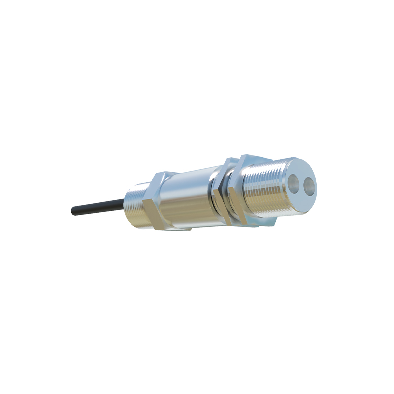
Identifying the Wires and Their Functions
Before proceeding with wiring, it is crucial to accurately identify each wire based on the sensor's datasheet or color-coding standards. Typically, the brown wire connects to the positive DC voltage supply (e.g., +12V to +24V), providing the necessary power for the sensor's internal electronics and emitter. The blue wire is connected to the common ground or negative terminal of the power source, completing the circuit. The output wire, often black or another color, carries the switching signal to the load, such as a programmable logic controller (PLC) input or a relay. Some sensors may have additional markings like "L+" for power, "L-" for ground, and "OUT" for output. Always verify these details, as incorrect connections can lead to malfunctions or permanent damage.
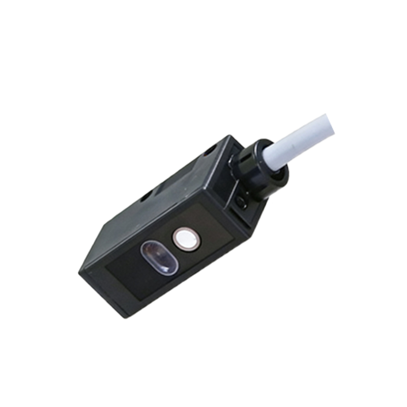
Step-by-Step Wiring Procedure
To wire a 3-wire photoelectric sensor, begin by ensuring the power supply is turned off to avoid electrical hazards. First, connect the brown wire to the positive terminal of your DC power source, which should match the sensor's voltage rating (commonly 12-24V DC). Next, attach the blue wire to the negative terminal or ground of the power supply. Finally, link the output wire (e.g., black) to the input of your control device, such as a PLC. If the sensor has a normally open (NO) or normally closed (NC) output, confirm the configuration aligns with your system requirements. Use appropriate wire gauges and secure connections with terminal blocks or connectors to prevent loose contacts. After wiring, double-check all connections against the schematic before powering on the system.
Common Wiring Configurations and Load Connections
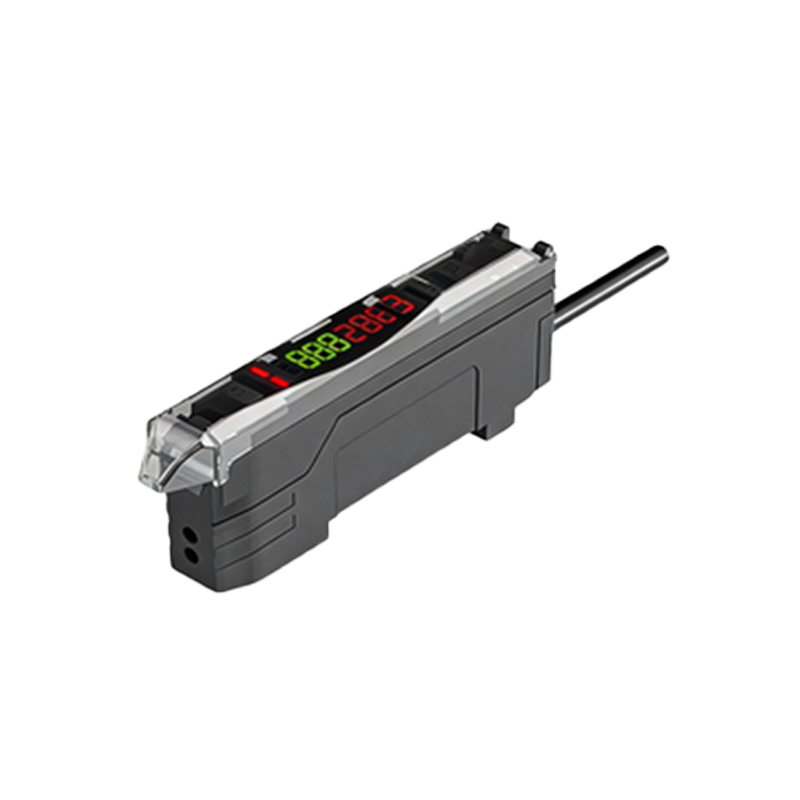
3-wire photoelectric sensors can be wired in two primary configurations based on the output type: sourcing (PNP) or sinking (NPN). In a sourcing configuration, the output wire provides a positive voltage to the load when activated, suitable for PLCs with sinking inputs. Conversely, in a sinking setup, the output connects the load to ground when triggered, ideal for sourcing PLC inputs. The load, such as a relay coil or indicator light, is typically connected between the output wire and the opposite power terminal. For instance, in a PNP sensor, the load is placed between the output and ground. Ensure the load's current and voltage ratings do not exceed the sensor's specifications to avoid overheating or failure. Diagrams in the sensor manual can guide proper setup for specific applications.
Troubleshooting and Best Practices
If a 3-wire photoelectric sensor fails to operate correctly, start by checking the power supply voltage with a multimeter to ensure it is within the specified range. Verify all wire connections for tightness and correctness, and inspect for any short circuits or damaged insulation. Test the sensor's response by observing the output indicator LED, if available, while interrupting the light beam. If the output is erratic, consider environmental factors like ambient light interference, dirt on the lens, or misalignment. For reliable performance, install sensors away from direct sunlight, clean lenses regularly, and use shielded cables in electrically noisy environments. Adhering to manufacturer guidelines and periodic maintenance can extend sensor life and reduce downtime in automation systems.
Applications and Advantages of 3-Wire Sensors
3-wire photoelectric sensors are widely used in industries such as packaging, material handling, and automotive manufacturing for tasks like object detection, counting, and position sensing. Their key advantages include simplified wiring compared to 2-wire types, which can have voltage drop issues, and better isolation between power and signal circuits, reducing the risk of false triggers. The separate output wire allows for direct interfacing with various control systems without additional components. Moreover, these sensors often support both NO and NC outputs, offering flexibility in logic design. By mastering 3-wire sensor wiring, engineers can enhance system efficiency, improve safety, and streamline automation processes effectively.