Introduction to Through-Beam Photoelectric Sensors
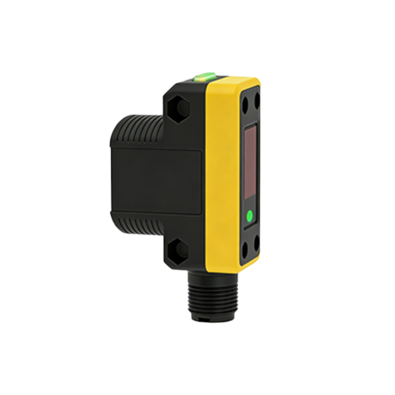
Through-beam photoelectric sensors, also known as opposed-mode sensors, consist of two separate units: a transmitter and a receiver. The transmitter emits a continuous beam of light, typically infrared or visible red, which is detected by the receiver. When an object interrupts this beam, the sensor's output state changes, triggering a control action. These sensors are highly valued in industrial automation for their long sensing ranges, high reliability, and immunity to object color, reflectivity, or surface texture. The 4-wire configuration is one of the most common designs, providing both a switched output and a direct connection to the power supply, offering flexibility for various control circuits.
Understanding the 4-Wire Configuration
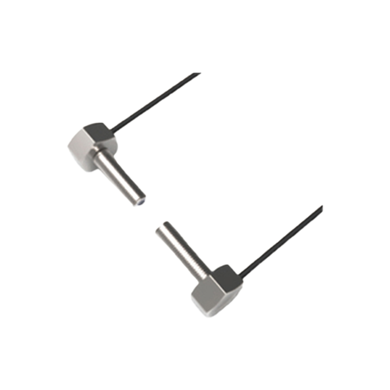
A standard 4-wire photoelectric sensor has four distinct terminals or lead wires, each with a specific function. The wire colors are typically standardized according to international conventions, though it is crucial to always consult the specific manufacturer's datasheet. The common configuration is as follows: Brown wire: This is the positive supply voltage line (+V). It connects to the positive terminal of the DC power source, usually in the range of 10-30 VDC. Blue wire: This is the negative supply voltage line or common ground (0V). It connects to the negative terminal of the DC power source. Black wire: This is the output signal line. In a normally open (NO) configuration, this wire switches to supply voltage when the light beam is interrupted (dark-on operation). White wire: This is often a second output or a complementary signal. It may be configured as normally closed (NC) or for a different output type (e.g., NPN vs. PNP). The exact function of the white wire varies by model and must be verified.
Detailed Wiring Diagram and Procedure
The wiring process connects the sensor to a DC power supply and a load, such as a programmable logic controller (PLC) input, relay, or indicator lamp. First, establish the power circuit. Connect the brown wire from the sensor to the positive terminal (+V) of your 24 VDC power supply. Connect the blue wire from the sensor to the negative terminal (0V/COM) of the same power supply. This provides operational power to the sensor's internal electronics. Next, connect the output circuit. The load is connected between the output wire and the power supply. For a standard NPN sinking output (common in many regions), connect one side of the load (e.g., the PLC input terminal) to the positive supply (+V). Connect the other side of the load to the sensor's black output wire. When the beam is blocked, the NPN transistor inside the sensor switches on, sinking current from the load to the blue wire (0V), thus completing the circuit and activating the load. For the white wire, if used, refer to the manual to determine if it requires connection to a second load or if it should be insulated and left unused.
PNP vs. NPN Output Sourcing Considerations
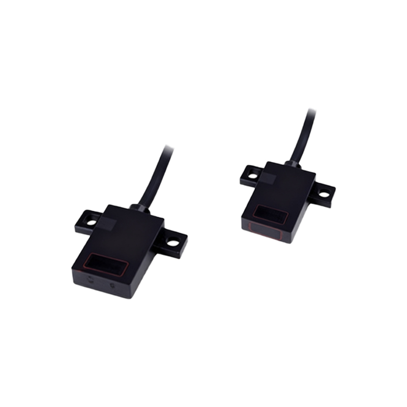
A critical aspect of wiring 4-wire sensors is identifying whether the output is PNP (sourcing) or NPN (sinking). This determines how the load is connected relative to the power supply. The wiring diagram described above is for an NPN sensor. For a PNP sensor, the output logic is reversed. The black wire would be the positive output. In this case, one side of the load is connected to the blue wire (0V). The other side of the load is connected to the sensor's black wire. When activated, the PNP transistor sources current from the brown wire (+V) through the load to the blue wire (0V). Misidentifying the output type is a common installation error that prevents proper operation. Many modern 4-wire sensors offer a selectable or configurable output type, which must be set correctly before wiring.
Practical Installation and Alignment Tips
Proper physical installation is as important as correct electrical wiring. Securely mount the transmitter and receiver units on stable surfaces, ensuring they are perfectly aligned opposite each other. The sensing beam must be perpendicular to the path of the target object. Use the sensor's built-in alignment indicators, often LED lights that change color or blink when optimal alignment is achieved. For long-range applications, ensure the units are rigidly fixed to prevent vibration from misaligning the beam. Consider environmental factors: protect the lens from dust, moisture, and direct sunlight, which can cause false triggers. Use conduit or cable carriers to protect the wires from physical damage and electrical noise in industrial environments. After wiring and alignment, perform a functional test by passing an object through the beam to verify the output switches reliably.
Troubleshooting Common Wiring Issues
Several issues can arise from incorrect wiring. If the sensor's power indicator LED does not illuminate, check the polarity and voltage of the power connections to the brown and blue wires. A reversed connection can damage the sensor. If the power LED is on but the output does not activate, verify the output type (PNP/NPN) and the load connection. Ensure the load's voltage and current ratings are compatible with the sensor's output specifications. An oscilloscope or multimeter can be used to check for a voltage change on the black output wire when the beam is blocked. Intermittent operation may be caused by poor alignment, insufficient power supply current, or electrical interference. Ensure all connections are tight and that cables are not running parallel to high-voltage AC power lines. Always disconnect power before making or changing any wiring connections.
Conclusion and Best Practices
Correctly wiring a 4-wire through-beam photoelectric sensor is fundamental to ensuring reliable operation in automated systems. Always start by consulting the manufacturer's documentation for the specific wiring diagram, terminal designations, and output configuration. Double-check the power supply requirements and the sourcing/sinking nature of the output before connecting any wires. Use proper tools to make secure connections and adhere to local electrical codes and safety standards. Proper installation, combined with routine maintenance and environmental protection, will maximize the sensor's lifespan and performance, providing accurate and consistent object detection for your application.