Introduction to 3L Photoelectric Sensors
3L photoelectric sensors are widely used in industrial automation for detecting the presence, absence, or position of objects without physical contact. These sensors operate by emitting a light beam (typically infrared, visible red, or laser) and detecting changes in the received light intensity caused by an object interrupting or reflecting the beam. Their reliability, fast response time, and versatility make them essential components in packaging, material handling, assembly, and safety systems. Understanding the correct wiring is fundamental to ensuring optimal performance, system safety, and longevity of both the sensor and the connected control equipment.
Understanding Sensor Components and Terminals
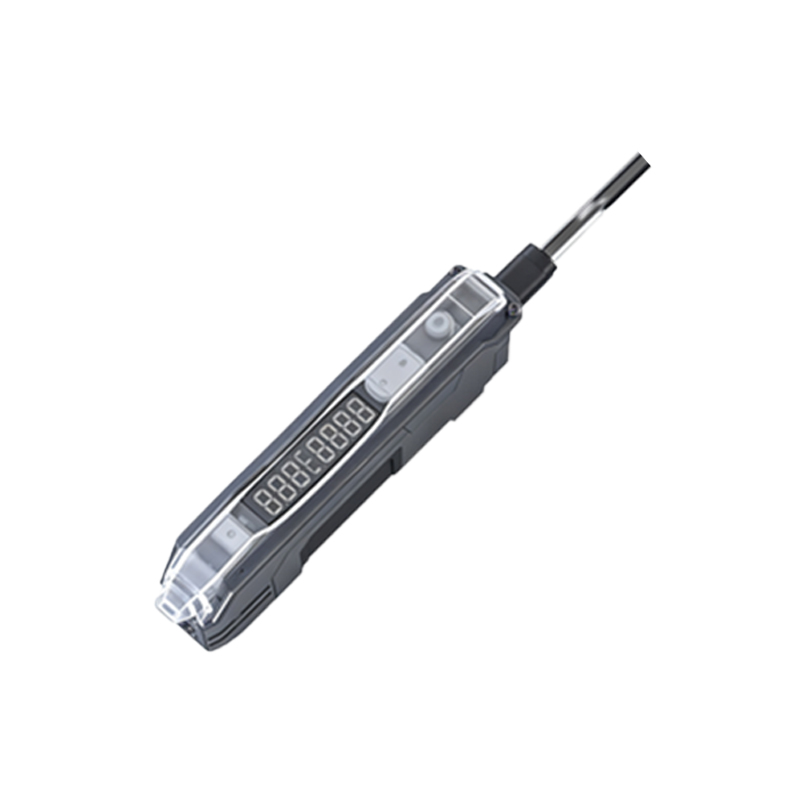
A standard 3L photoelectric sensor housing contains several key terminals for connection. The specific labeling may vary slightly by model (e.g., diffuse, retro-reflective, or through-beam types), but the core terminals are consistent. Typically, you will find terminals for the power supply, output signal, and sometimes a function selector or timing adjustment. Common terminal designations include: V+ or Brown wire for DC positive supply voltage; V- or Blue wire for DC common or negative; Black wire for the output signal (normally open or normally closed); and White wire for a complementary output or control input. Some advanced models may have additional wires for diagnostic outputs, teach-in functions, or analog signal transmission. Always refer to the specific datasheet for your model's pinout.
Standard DC 3-Wire Wiring Configuration
The most common wiring setup is the 3-wire DC configuration. For an NPN (sinking) output sensor: Connect the Brown wire to the positive DC supply voltage (typically 10-30 VDC). Connect the Blue wire to the negative DC supply common (0V). The Black wire is the output. When the sensor detects an object, it switches the Black wire to connect to the negative common (sinks current). This Black wire is connected to the input of a PLC, relay, or controller. For a PNP (sourcing) output sensor: The Brown (V+) and Blue (V-) connections remain the same. However, when activated, the Black output wire switches to connect to the positive supply voltage (sources current). It is crucial to match the sensor's output type (NPN/PNP) with the input requirements of your receiving device to avoid malfunction.
Connecting to a Programmable Logic Controller (PLC)
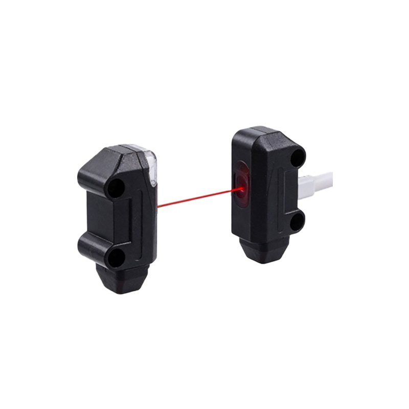
Integrating a 3L sensor with a PLC is a standard application. First, ensure the sensor's voltage range matches the PLC's supply. For an NPN sensor connected to a PLC sinking input module: Wire the sensor's Black output to the PLC's input terminal. The PLC input's common is typically connected to positive voltage. When the sensor activates, it completes the circuit to negative, signaling the PLC. For a PNP sensor connected to a PLC sourcing input module: The sensor's Black output connects to the PLC input. The PLC input's common is connected to negative. Upon activation, the sensor provides positive voltage to the input. Always include a protective fuse (e.g., 1-2A) in the positive supply line and follow proper grounding practices to shield against electrical noise.
Wiring for Relay and Load Control
For directly controlling a relay, solenoid, or indicator lamp, careful consideration of the load current is necessary. The sensor's output has a maximum switching capacity (e.g., 100mA). If the load exceeds this, you must use an interposing relay. Wire the sensor's output to the coil of the interposing relay. Then, use the contacts of that relay to control the higher-power load. Connect a free-wheeling diode (for DC coils) or a snubber circuit (for AC coils) across the relay coil to suppress voltage spikes that could damage the sensor's output transistor. Ensure the load's operating voltage is within the sensor's output rating. This setup isolates the sensitive sensor electronics from potentially damaging inductive kickback from the load.
Power Supply Considerations and Noise Immunity
A stable, clean power supply is critical. Use a regulated DC power supply with adequate current capacity. Ripple and voltage fluctuations can cause erratic sensor operation. For long cable runs, consider using a slightly higher supply voltage to compensate for voltage drop. To enhance noise immunity in electrically noisy environments, use shielded cables. Connect the cable shield to earth ground at the power supply end only, avoiding ground loops. Keep sensor cables away from high-voltage power lines, motor drives, and welding equipment. If using multiple sensors, it is often advisable to use a single, adequately sized power supply with separate fusing for each sensor or small group of sensors.
Troubleshooting Common Wiring Issues
Several symptoms point to wiring problems. If the sensor's indicator LED does not light, check power and ground connections and verify voltage at the sensor terminals. If the output seems stuck on or off, verify the output type (NPN/PNP) compatibility with the load. A constantly activated sensor might indicate incorrect wiring of the control input (e.g., white wire) or a wiring short. Intermittent operation often stems from loose connections, insufficient power supply capacity, or electrical noise interference. Use a multimeter to check continuity and voltage levels systematically. Always disconnect power before making or changing wiring connections to prevent short circuits and equipment damage.
Safety Precautions and Best Practices
Always de-energize the electrical circuit before installing or wiring the sensor. Use tools with insulated handles. Confirm the sensor's operating voltage before applying power. Securely tighten terminal screws to prevent arcing and overheating. Use wire ferrules on stranded wires for a more reliable connection in screw terminals. Route cables neatly in cable ducts or conduits to prevent physical damage. For safety-critical applications (e.g., light curtains or muting sensors), follow all applicable standards (like IEC 61496) and perform a validated risk assessment. Regularly inspect wiring for signs of wear, corrosion, or damage as part of a preventive maintenance program.