Understanding Proximity Sensor Fundamentals
Proximity sensors are critical non-contact devices in industrial automation, detecting the presence or absence of objects within their sensing range. They operate on various principles, including inductive, capacitive, ultrasonic, and photoelectric technologies. Inductive sensors, common in metal detection, generate an electromagnetic field. A metallic target entering this field induces eddy currents, causing a change in oscillation amplitude that triggers the sensor's output switch. Capacitive sensors detect both metallic and non-metallic materials by measuring changes in capacitance. Understanding these operational principles is the first step in diagnosing why a sensor might fail. A sensor does not simply "break"; its performance degrades due to specific, often preventable, factors.
Primary Causes of Premature Sensor Failure
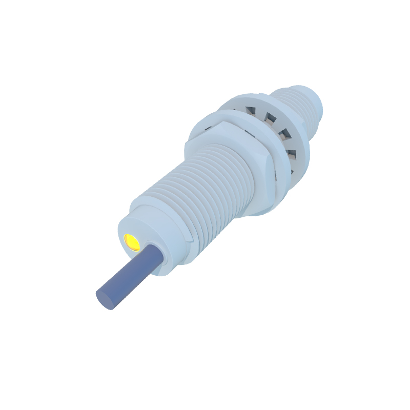
Environmental stressors are the leading cause of premature proximity sensor damage. Excessive heat from nearby machinery or ambient conditions can degrade internal electronic components, solder joints, and housing materials. Conversely, extreme cold can make plastics brittle and affect signal stability. Physical impact and vibration, prevalent in heavy machinery applications, can crack sensor housings, loosen internal connections, or misalign sensing elements. Chemical exposure is another silent killer; oils, coolants, solvents, and even certain cleaning agents can corrode the sensor face or housing, leading to ingress and internal damage. Electrical overloads, such as voltage spikes, incorrect wiring, or short circuits, can instantly destroy the sensor's output circuit or power supply section.
Step-by-Step Diagnostic Procedures
Effective troubleshooting begins with a systematic approach. First, perform a visual inspection. Check for obvious physical damage, cracks, corrosion on the sensing face, or loose cabling. Ensure the sensor is clean and properly mounted. Next, verify the electrical supply. Use a multimeter to confirm that the voltage at the sensor's terminals matches the specified range, both under no-load and loaded conditions. Then, test the sensor's output. For a digital sensor, observe the output LED indicator while bringing a valid target into the sensing range. Simultaneously, measure the output signal with a meter or oscilloscope to ensure it switches cleanly and provides the correct voltage or current. If the sensor is analog, measure the output signal across its entire range of operation. Always consult the manufacturer's datasheet for specific test points and tolerance values.
Analyzing Specific Failure Symptoms
Different failure modes present distinct symptoms. Intermittent operation often points to loose wiring connections, a failing cable due to constant flexing, or an unstable power supply. It can also indicate that the target is at the very edge of the sensor's sensing range. A sensor that fails to detect any target may have a completely damaged oscillator circuit (inductive), a blocked or dirty lens (photoelectric), or a severed coil. Conversely, a sensor that is permanently "on" might have a stuck output transistor due to an overload or its sensing field may be influenced by a nearby metallic object or electrical noise. Reduced sensing range is a common degradation symptom, typically caused by a buildup of debris on the sensing face, weakening internal components, or a declining power supply voltage.
Implementing Robust Prevention Strategies
Prevention is far more cost-effective than reactive repair. Start with correct selection. Choose a sensor with an appropriate IP (Ingress Protection) rating for the environment—IP67 for washdown areas, IP69K for high-pressure cleaning. Select the correct sensing technology and range for the application. Ensure proper installation: mount the sensor securely to minimize vibration, maintain the recommended mounting distances from metal surfaces to avoid mutual interference, and use shielded cables in electrically noisy environments. Implement protective electrical measures such as surge suppressors, proper grounding, and isolation relays to shield sensors from voltage transients. Establish a routine maintenance schedule that includes cleaning the sensor face, checking mounting integrity, and verifying electrical connections.
When to Repair and When to Replace
The decision to repair or replace a failed sensor depends on several factors. Most standard proximity sensors are sealed, non-serviceable units designed for replacement. Attempting to open the housing typically voids the warranty and may compromise its environmental sealing. Replacement is the only viable option for sensors with physical damage, severe corrosion, or internal electronic failure. However, if the issue is traced to an external factor like faulty cabling, a bad connector, or improper installation, repairing that external component is the correct course. For critical applications or expensive, specialized sensors, consulting the manufacturer for a repair or exchange program may be economical. Always document failure causes to identify patterns and address root issues in the system.
Advancements in Sensor Durability and Diagnostics
Modern proximity sensors incorporate features that enhance