Introduction to Photoelectric Sensors and Pneumatic Cylinders
In industrial automation, the integration of sensing and actuation components is fundamental for creating responsive and efficient systems. Photoelectric sensors and pneumatic cylinders represent two such critical elements. A photoelectric sensor operates by emitting a light beam, typically infrared, visible red, or laser, and detecting changes in the received light signal. These changes indicate the presence, absence, or position of an object. Pneumatic cylinders, on the other hand, are actuators that convert compressed air energy into linear mechanical motion. They are prized for their simplicity, high speed, and reliability in repetitive tasks. The connection between a photoelectric sensor and a cylinder forms the backbone of countless automated processes, such as part ejection, sorting, and precise positioning. This synergy allows a control system to make decisions based on real-time object detection, triggering the cylinder's extension or retraction to perform a physical action.
Core Components and Operating Principles
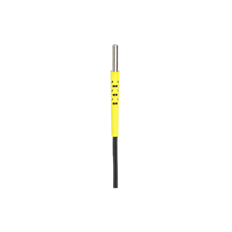
Understanding the individual components is key to a successful integration. A standard photoelectric sensor consists of an emitter, a receiver, and associated circuitry. They come in various sensing modes: through-beam (separate emitter and receiver), retro-reflective (uses a reflector), and diffuse (proximity) sensing. The sensor's output is typically a digital signal—either PNP (sourcing) or NPN (sinking)—that switches state when the target object is detected. A pneumatic cylinder comprises a piston, rod, and barrel. Its motion is controlled by a directional control valve, which ports compressed air to either side of the piston. The valve is itself actuated by an electrical signal, commonly 24V DC. Therefore, the photoelectric sensor does not connect directly to the cylinder's air lines but to the valve's solenoid coil or the programmable logic controller (PLC) that commands the valve.
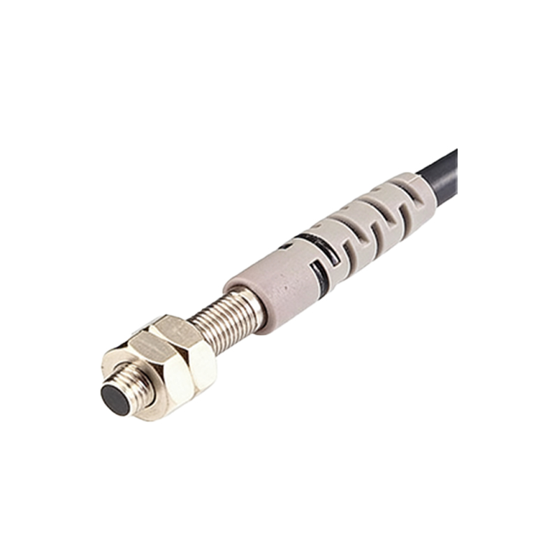
System Wiring and Electrical Interface
The electrical connection is the most critical step. For a basic direct control setup, the photoelectric sensor is wired in series with the solenoid valve of the cylinder. Consider a system using a 24V DC power supply, an NPN normally-open photoelectric sensor, and a single solenoid valve. The positive terminal of the power supply connects to one wire of the valve's solenoid. The other solenoid wire connects to the sensor's black (or output) wire. The sensor's blue wire is connected to the power supply's negative terminal, and the brown wire to the positive terminal. When the sensor detects an object, its internal NPN transistor switches, completing the circuit from the valve solenoid to negative, thus energizing the solenoid and causing the valve to shift. This shift ports air to the cylinder, extending the rod. For more complex sequences or multiple cylinders, the sensor outputs are typically wired to the digital input modules of a PLC, which then executes a control program to operate the valves via its output modules.
Control Logic and Sequencing
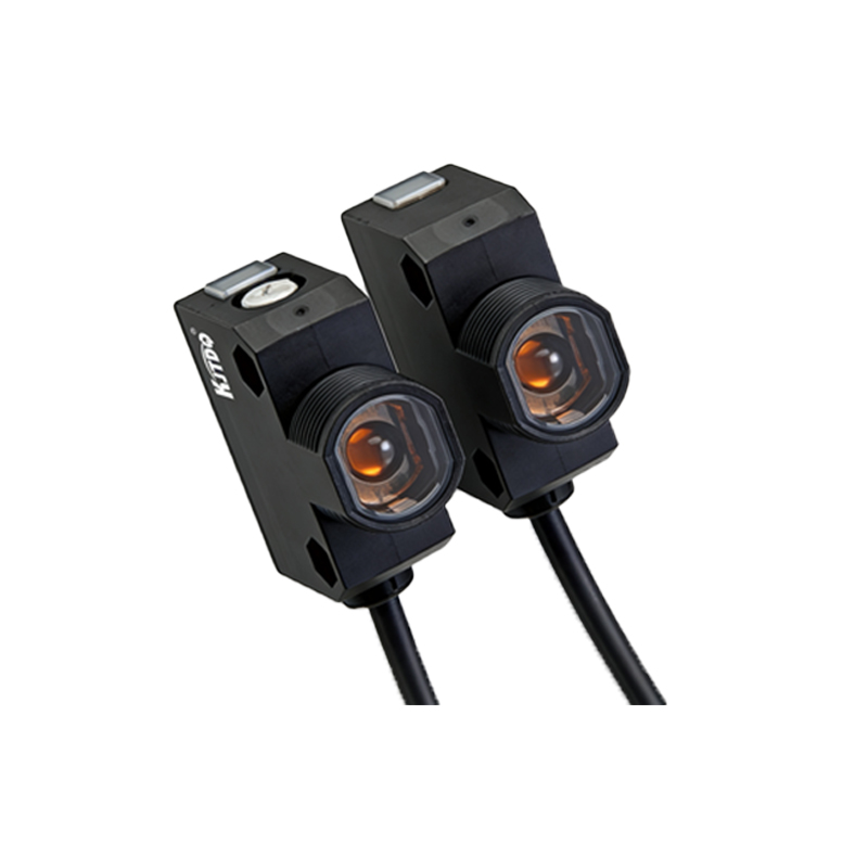
Implementing reliable control logic is essential for system robustness. In a PLC-based system, the photoelectric sensor acts as a conditional input. A simple ladder logic rung might use the sensor's input address as a condition to latch an output coil address assigned to the cylinder's valve. More advanced sequences involve timers, counters, and interlock conditions from other sensors. For instance, a sensor detecting a part on a conveyor could trigger a cylinder to push the part into a fixture. A second sensor in the fixture confirms proper placement before allowing the next cylinder in the sequence to actuate. This prevents machine damage and ensures process integrity. It is also common to use the sensor not only to initiate motion but also to verify its completion. A sensor positioned to detect the cylinder rod's fully extended or retracted position provides valuable feedback to the control system, confirming the action before proceeding to the next step.
Installation, Alignment, and Calibration Tips
Proper physical installation ensures optimal performance. Mount the photoelectric sensor securely on a stable bracket, ensuring it is protected from excessive vibration, which can cause false triggering. For through-beam and retro-reflective types, precise alignment between the emitter, receiver, or reflector is paramount. Use the sensor's built-in alignment indicator (often an LED) to achieve the strongest signal. Adjust the sensitivity potentiometer to reliably detect the target object while ignoring background interference or ambient light. For diffuse sensors, consider the target object's color, material, and size, as these affect reflectivity. Position the sensor so that the cylinder's moving rod or the target object passes consistently through the sensing window. Maintain a reasonable safety margin in the sensing distance to account for mechanical tolerances and wear over time.
Troubleshooting Common Connection Issues
Even with correct wiring, issues can arise. If the cylinder does not actuate, follow a systematic approach. First, verify power is present at the sensor and the valve solenoid. Use a multimeter to check voltage. Second, observe the sensor's status LED to confirm it is switching states when the target is presented. If it is not, check alignment, cleanliness of the lens, and sensitivity settings. Third, if the sensor is working but the solenoid is not energizing, check the continuity of the wiring between the sensor's output and the solenoid. Listen for an audible click from the valve when the sensor triggers. If the cylinder actuates erratically or weakly, check the air supply pressure and ensure the valve is correctly sized for the cylinder. Electrical noise from nearby motors or drives can sometimes interfere with sensor signals; using shielded cables and proper grounding can mitigate this.
Advanced Applications and Safety Considerations
Beyond basic on/off control, advanced configurations enhance functionality. Analog output photoelectric sensors can provide distance or intensity information, allowing for proportional control or more precise positioning tasks. Integrating multiple sensors with a single cylinder can create sophisticated state machines. For example, one sensor initiates extension, another verifies mid-stroke position, and a third confirms full retraction. Safety must never be compromised. Always lock out and tag out pneumatic and electrical power before installation or maintenance. Use dual-channel safety sensors with monitoring modules for applications where personnel interact with the machinery. Ensure that the system includes appropriate emergency stop circuits that are independent of the primary sensor control logic. Properly sized exhaust mufflers on the valve and cylinder ports are also important for noise reduction and operational safety.
Conclusion and Best Practices
Connecting a photoelectric sensor to a pneumatic cylinder is a foundational skill in automation. The process involves a clear understanding of electrical interfaces, logical control sequences, and meticulous physical setup. Best practices include: always consulting the datasheets for the specific sensor and valve models, using a PLC for complex or multi-step processes to ensure flexibility and diagnostics, implementing sensor feedback to confirm cylinder positions, and adhering to all relevant electrical and machinery safety standards. By mastering this integration, engineers can build reliable, efficient, and intelligent automated systems that respond accurately to their environment, driving productivity and precision in modern manufacturing.