Understanding Proximity Sensor Fundamentals
Proximity sensors are indispensable components in modern industrial automation, providing non-contact detection of objects within a defined sensing range. Their ability to operate without physical contact ensures longevity, reliability, and high-speed operation in demanding environments. The core principle involves generating an electromagnetic field or beam and detecting changes caused by a target object. Selecting the correct sensor for a specific application is a critical engineering task that directly impacts system performance, safety, and cost-effectiveness. A systematic approach using a detailed parameter table is essential to navigate the vast array of available technologies, including inductive, capacitive, ultrasonic, and photoelectric sensors. This guide outlines the key parameters engineers must evaluate to make an informed selection.
Core Electrical and Sensing Parameters
The electrical and sensing characteristics form the foundation of the selection process. The operating voltage range is paramount; sensors are commonly available for DC (10-30V DC) or AC (90-250V AC) supplies. The output configuration must be specified: NPN (sinking) or PNP (sourcing) for DC sensors, and normally open (NO) or normally closed (NC) contact logic. The sensing distance, or nominal range (Sn), is the rated operating distance for a standard target. Engineers must also consider the assurance factor, typically applying a derating of 10-20% to account for temperature fluctuations, voltage variations, and manufacturing tolerances. Response time, the delay between target detection and output switching, is crucial for high-speed applications. Finally, the current consumption and available output current (load current) must be compatible with the control system's PLC or input module specifications.
Physical and Environmental Specifications
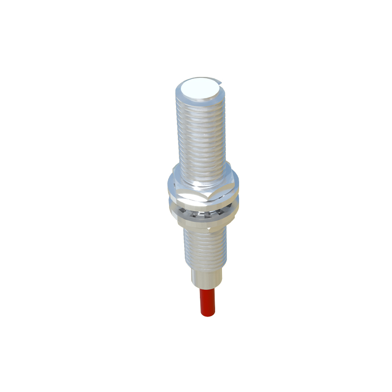
The sensor's housing and construction must withstand the installation environment. The housing material, typically nickel-plated brass, stainless steel, or PBT plastic, is selected based on required mechanical strength and chemical resistance. The ingress protection (IP) rating, such as IP67 or IP69K, defines the level of protection against dust and liquids. Temperature range, both operational and storage, must encompass the application's extremes. For harsh environments, resistance to specific chemicals, oils, or coolants is a key consideration. The physical size and shape (barrel, rectangular, ring-shaped) are determined by spatial constraints in the machinery. Connection type, whether pre-wired cable, quick-disconnect (M8, M12 connectors), or terminal block, affects installation and maintenance ease.
Target Material and Application-Specific Factors
For inductive sensors, the target material is a primary driver. Standard sensors detect ferrous metals (like steel) at the rated sensing distance. For non-ferrous metals (aluminum, copper, brass), the effective sensing distance is reduced, and special factor-1 sensors are available. Capacitive sensors detect nearly any material, including liquids and plastics, making material composition a critical parameter. The target shape, size, and approach direction (axial or lateral) also influence performance; a target should ideally be larger than the sensor's face. In applications involving multiple sensors mounted closely, mutual interference must be prevented by selecting models with built-in synchronization or by maintaining minimum separation distances.
Advanced Functional Parameters
Modern proximity sensors offer advanced features that solve specific application challenges. Switching frequency defines how many on/off cycles per second the sensor can handle. Short-circuit and overload protection safeguards the sensor and circuit. For precise positioning tasks, sensors with analog current (4-20mA) or voltage (0-10V) outputs provide continuous distance measurement. IO-Link enabled sensors offer digital communication for parameter setting, process data monitoring, and advanced diagnostics directly to the controller. Certain models feature weld-field immunity (M12 or M18 coding) for reliable operation near resistance welding equipment. Embedded diagnostics, like LED status indicators for power, output, and error conditions, greatly simplify troubleshooting.
Constructing and Utilizing the Selection Table
A practical selection parameter table consolidates all these criteria. Engineers should create a spreadsheet or checklist with columns for each parameter: Sensor Type (Inductive/Capacitive/etc.), Sensing Distance, Supply Voltage, Output Type, Housing Material, IP Rating, Temperature Range, Target Material, and Special Features. The first step is to define the non-negotiable application requirements: target material, required sensing distance, environmental conditions, and required output signal. This immediately narrows the field. Next, match these against manufacturer datasheets, populating the table with compatible models from various vendors. A side-by-side comparison highlights trade-offs in performance, size, cost, and availability, leading to an optimal, justified selection that ensures robust and reliable system integration.