Fundamental Principles of Two-Phase Photoelectric Sensing
Two-phase photoelectric sensors, also known as quadrature output sensors, are a specialized category of proximity devices that provide more information than standard on/off sensors. At their core, they operate on the same basic principle as standard through-beam or retro-reflective sensors: an emitter sends a light beam (typically infrared, red, or laser) to a receiver. The key differentiator lies in the receiver's internal configuration. Instead of a single photodetector element, a two-phase sensor incorporates two closely spaced photodetectors. When a moving object, often a codewheel or codestrip with alternating opaque and transparent segments, interrupts or allows the light beam to pass, it creates two output signals. These signals, typically labeled Channel A and Channel B, are identical in frequency but are offset by a precise phase shift—usually 90 electrical degrees. This phase relationship is the origin of the "two-phase" designation and is critical for determining direction.
Understanding the Quadrature Output Signal
The quadrature output is the defining characteristic of these sensors. The two square wave signals, A and B, are generated as the target moves. By analyzing the phase relationship between these two channels, a connected controller or counter can decipher not just the presence or speed of an object, but also its direction of travel. For instance, if Channel A leads Channel B (A goes high before B when moving forward), the system interprets this as forward motion. Conversely, if Channel B leads Channel A, it indicates reverse motion. This directional data is invaluable in applications like conveyor systems, rotary encoders, and automated guided vehicles (AGVs) where understanding movement direction is essential for precise control and positioning. The 90-degree phase shift also allows for increased resolution; by counting both the rising and falling edges of both signals, the system can achieve four times the resolution of a single-channel sensor, a technique known as 4X decoding.
Key Components and Sensor Construction
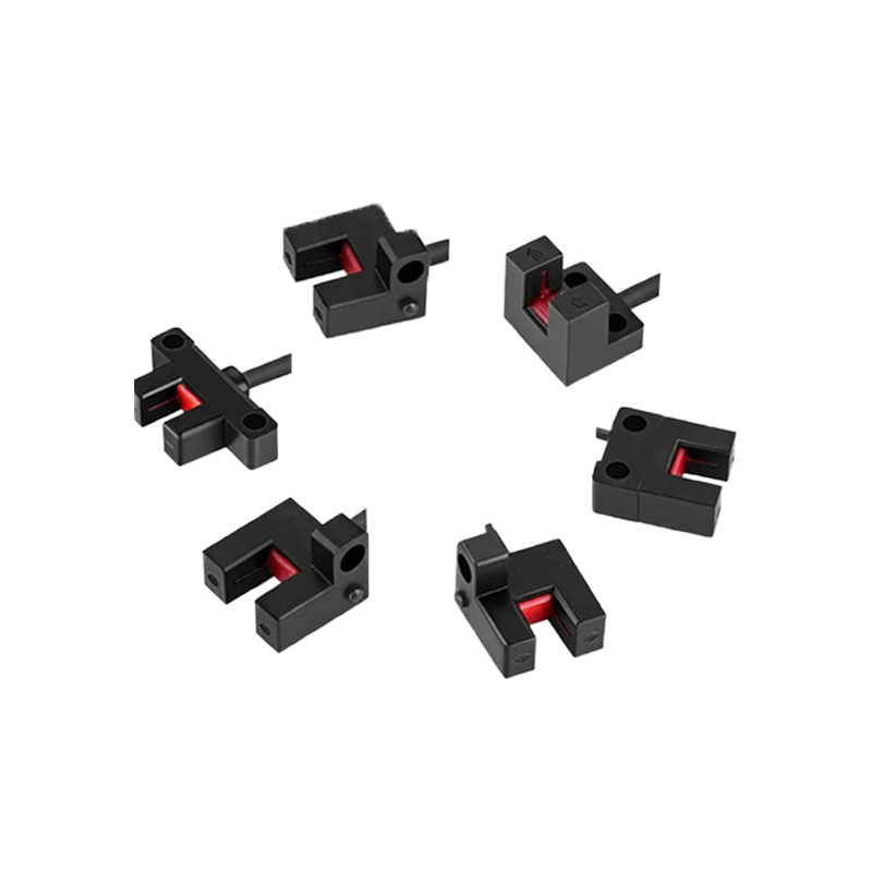
A typical two-phase photoelectric sensor assembly consists of several key components engineered for industrial durability. The emitter side houses a light-emitting diode (LED) or laser diode, chosen for its long life and stable output. The receiver side contains the dual photodetector array, which is precisely aligned to generate the required phase shift. Between them, the target codewheel or strip is manufactured with high precision to ensure consistent signal generation. The sensor housing is robust, often rated IP67 or higher, to withstand harsh environments containing dust, moisture, and vibration. Integrated electronics condition the photodetector signals, converting them into clean, amplified digital square waves compatible with PLCs, motor drives, and dedicated counter modules. Many models feature adjustable mounting brackets for precise alignment and may include LED indicators for channel status to aid in installation and troubleshooting.
Primary Industrial Applications and Use Cases
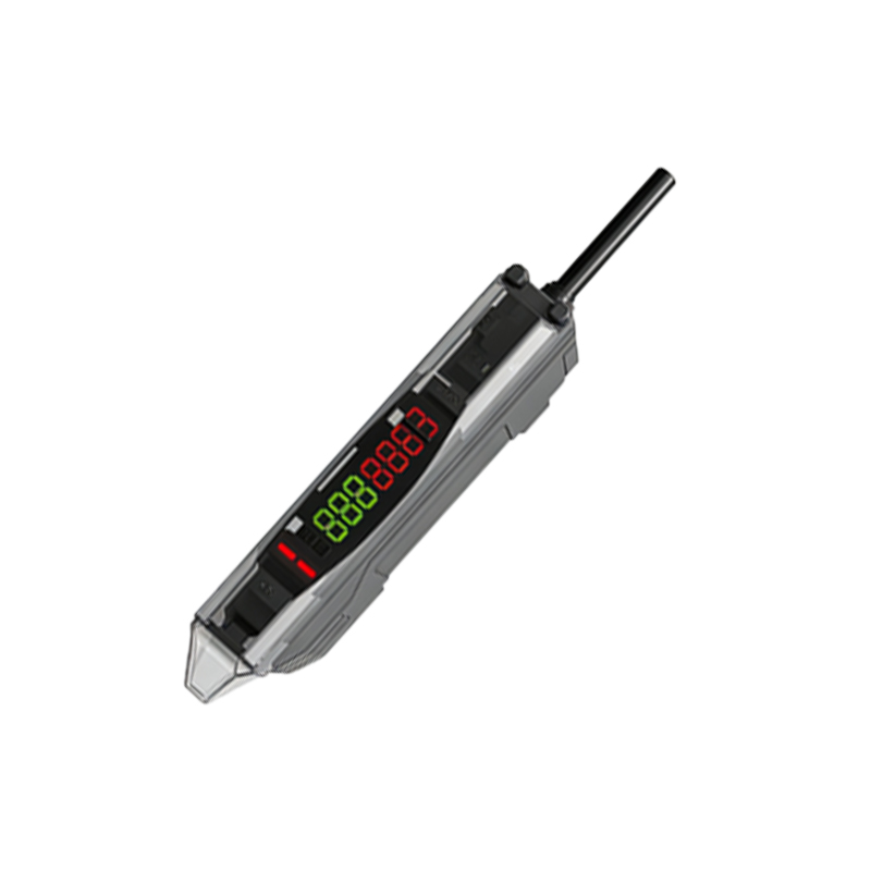
The unique capabilities of two-phase photoelectric sensors make them indispensable in numerous industrial automation scenarios. One of the most common applications is in rotary and linear encoders for servo and stepper motors, providing feedback for precise speed and position control in CNC machines, robotics, and packaging equipment. In material handling, they monitor the direction and speed of conveyors, detect jams, and count products with directional context. They are crucial in web processing lines (for textiles, paper, or film) to control tension and detect edge guidance by tracking lateral movement. Automated storage and retrieval systems (AS/RS) use them to verify shuttle direction and position. Furthermore, in printing machinery, they ensure registration control by monitoring the position of printing cylinders or the paper feed with directional awareness, preventing costly misalignment.
Advantages Over Single-Phase and Other Sensor Types
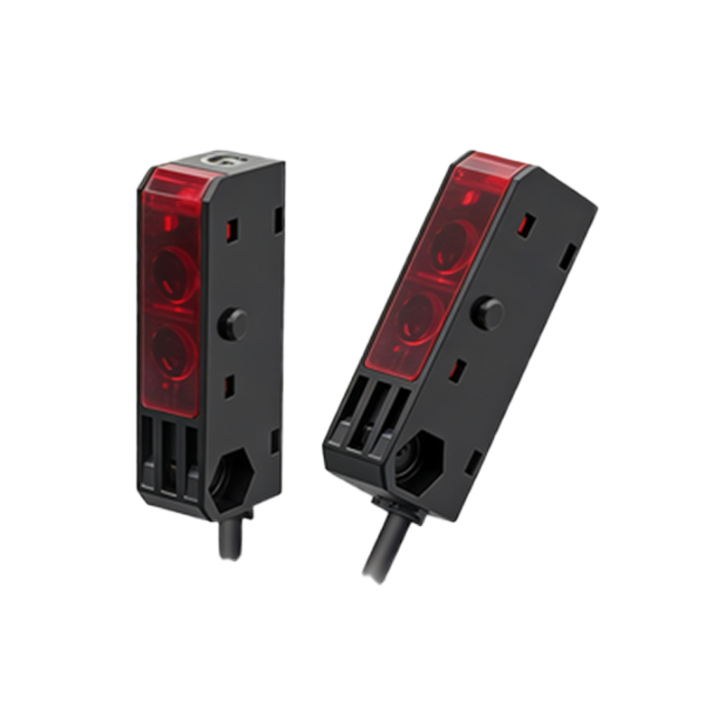
Compared to standard single-output photoelectric sensors, two-phase models offer significant functional advantages. The foremost is bidirectional sensing, adding a critical dimension of data for complex motion control. The inherent 4X resolution multiplication provides higher precision without requiring a finer physical pattern on the target, which can be more expensive to manufacture. They offer high noise immunity because the differential nature of the two signals helps reject common-mode electrical interference. When compared to purely magnetic or inductive sensors for rotary encoding, photoelectric versions can achieve much higher resolutions and speeds, and they can work with non-ferrous materials. However, they may be more susceptible to certain environmental contaminants like heavy oil mist or dust, which has led to the development of sealed optical blocks and air-purge options for demanding installations.
Critical Selection Criteria for System Integration
Selecting the appropriate two-phase photoelectric sensor requires careful consideration of several technical parameters. First, determine the required resolution, which dictates the pitch of the target pattern and the sensor's ability to resolve it. The response frequency or maximum switching speed must exceed the operational speed of the application. The sensing distance and gap tolerance between the sensor and target are vital for mechanical design. Environmental factors are paramount; the sensor's IP rating, temperature range, and resistance to chemicals must match the operating conditions. Electrical output type (e.g., NPN open collector, push-pull, or line driver) must be compatible with the controller's input card. Finally, mechanical form factor, mounting style, and alignment features must suit the available space and assembly process. Consulting datasheets and application engineers is highly recommended to ensure optimal performance and reliability.
Installation Tips and Maintenance Best Practices
Proper installation is crucial for reliable operation. Ensure precise alignment between the emitter, receiver, and the path of the target; even minor misalignment can degrade signal quality or cause a channel to drop out. Use the sensor's built-in alignment indicators if available. Secure all mounting hardware to prevent vibration-induced drift. Maintain the recommended gap between the sensor face and the target, and keep the optical surfaces clean from dust, oil, and debris using appropriate cleaners and lint-free wipes. During wiring, follow EMC guidelines: use shielded cables, ground the shield properly at the controller end, and separate sensor cables from power lines to minimize electrical noise. Periodically verify signal integrity using an oscilloscope to check for clean square waves with a stable 90-degree phase relationship. Implementing these practices maximizes sensor lifespan and system uptime.