Understanding Proximity Sensor Fundamentals
Proximity sensors are indispensable components in modern industrial automation, detecting the presence or absence of an object without physical contact. Their operation relies on electromagnetic fields, infrared light, or ultrasonic sound waves. Correct wiring is paramount, not only for the sensor to function but also to ensure the safety of personnel and equipment, prevent damage to the sensor and the connected controller (typically a PLC), and guarantee system reliability. A single wiring error can lead to sensor failure, machine downtime, or even hazardous situations. This guide provides a clear, step-by-step explanation of wiring diagrams for the most common types of proximity sensors used in industrial settings.
Key Components and Wire Color Standards
Before examining specific diagrams, it is crucial to understand the standard terminal designations and wire colors, which are often consistent across manufacturers but should always be verified against the specific sensor's datasheet. A typical 3-wire DC sensor will have the following connections: Brown wire: This is the positive supply voltage wire (+V or V+). It connects to the positive terminal of the DC power source, commonly 10-30V DC. Blue wire: This is the negative supply voltage wire (0V, COM, or V-). It connects to the negative terminal of the DC power source, completing the sensor's internal circuit. Black wire: This is the output signal wire. The state of this wire (switched on or off) changes based on the detection of a target. For a PNP (sourcing) sensor, the black wire supplies positive voltage to the load when activated. For an NPN (sinking) sensor, the black wire provides a path to ground (0V) when activated. Some sensors may have additional wires for diagnostic functions or a separate output.
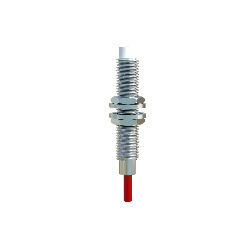
Wiring a 3-Wire DC PNP (Sourcing) Proximity Sensor
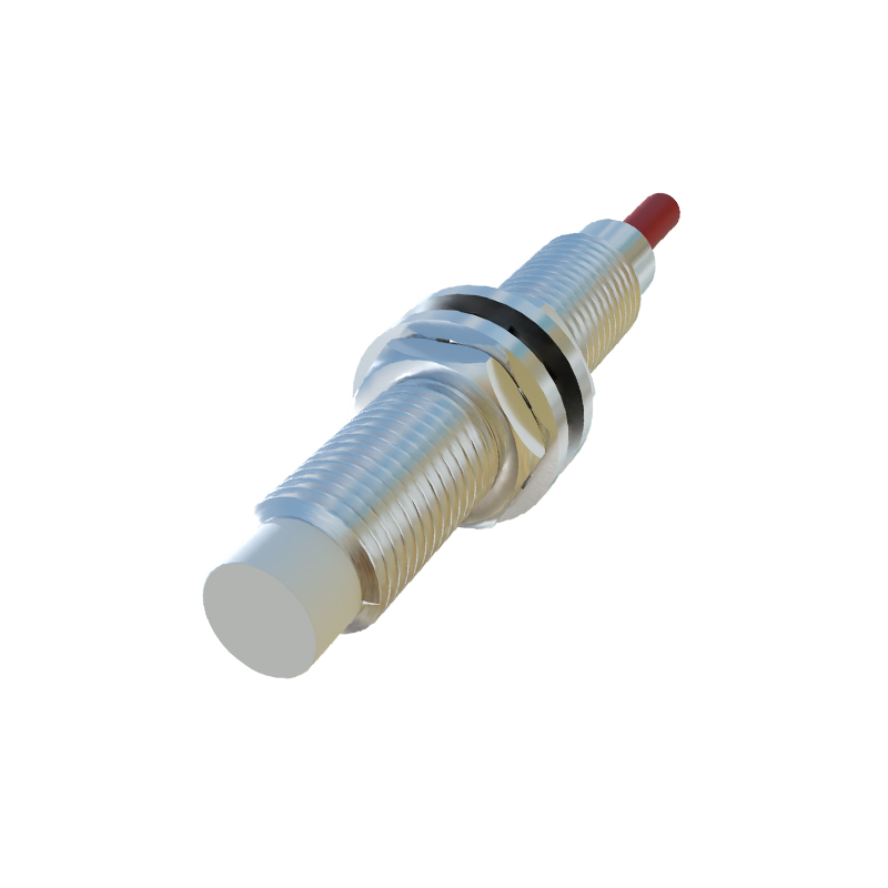
The PNP type is a very common configuration. In this setup, the sensor's output switch is connected between the positive supply and the output wire. Follow this procedure: First, connect the brown wire from the sensor to the positive terminal (+V) of your DC power supply (e.g., +24V DC). Second, connect the blue wire from the sensor to the negative terminal (0V) of the same DC power supply. The sensor now has power. Third, connect the black (output) wire from the sensor to one terminal of your load (e.g., the input channel of a PLC, a relay coil, or a pilot light). Finally, connect the other terminal of your load back to the negative terminal (0V) of the power supply. When the sensor detects a target, it internally connects the black wire to the positive supply (brown wire), "sourcing" current out through the black wire, through the load, and back to the negative supply, thus activating the load.
Wiring a 3-Wire DC NPN (Sinking) Proximity Sensor
The NPN type is equally common and functions as the complement to the PNP. Here, the sensor's output switch is connected between the output wire and the negative supply. The wiring steps are: Connect the brown wire to the positive supply (+V). Connect the blue wire to the negative supply (0V). Now, connect one terminal of your load to the positive supply (+V). Connect the other terminal of your load to the black (output) wire from the sensor. When the sensor detects a target, it internally connects the black wire to the negative supply (blue wire), "sinking" current from the load, through the black wire, and to ground. This completes the circuit and activates the load. It is critical never to interchange PNP and NPN wiring, as this will prevent operation and may cause damage.
Connecting to a Programmable Logic Controller (PLC)
Integrating a proximity sensor with a PLC is a standard application. The process follows the same principles above, where the PLC's input module acts as the load. For a PNP sensor, the black wire connects to the specific PLC input point (e.g., I0.0). The common terminal (COM) of that PLC input group must be connected to 0V. The sensor's brown and blue wires connect to the external +24V and 0V power supply, respectively. For an NPN sensor, the black wire still connects to the PLC input point. However, the common terminal (COM) of that PLC input group must be connected to +24V. The sensor's power connections remain the same. Always confirm the PLC input module's specifications (sinking or sourcing) to ensure compatibility with your sensor type.