Understanding the Proximity Sensor Magnetic Core
The magnetic core is a fundamental component in inductive proximity sensors, responsible for concentrating the magnetic field generated by the sensor's coil. This concentration enhances the sensor's sensitivity and detection range for metallic targets. Proper wiring is critical not only for functionality but also for ensuring operational safety, system stability, and longevity of the device. Before beginning any wiring procedure, always consult the specific manufacturer's datasheet for your sensor model, as pin configurations, voltage ratings, and output types (PNP vs. NDP) can vary significantly.
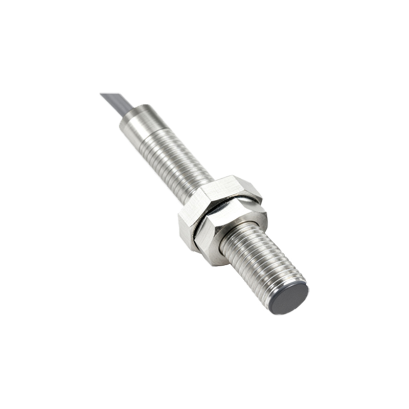
Essential Pre-Wiring Considerations and Safety
Prior to connecting any wires, a thorough assessment of the operating environment and electrical specifications is mandatory. First, identify the sensor's supply voltage requirement, commonly 10-30V DC or 20-250V AC. Using an incorrect power source can cause immediate and permanent damage. Next, determine the output type: a PNP (sourcing) sensor switches the positive voltage to the load, while an NPN (sinking) sensor switches the negative or ground path. The load (e.g., a PLC input, relay, or indicator light) must be compatible with this output configuration. Always disconnect power from the entire control circuit before initiating wiring work. Verify that the cable gland or connector entry is properly sealed if the sensor is used in damp or dusty conditions.
Wiring a 3-Wire DC Proximity Sensor
The three-wire DC sensor is the most prevalent type in industrial automation. Its cable typically contains a brown wire, a blue wire, and a black wire (colors may vary; always check the manual). The standard configuration is as follows: connect the brown wire to the positive terminal of your DC power supply. Connect the blue wire to the negative terminal or common ground (0V). The black wire is the signal output wire. For a PNP sensor, this black wire will provide the positive supply voltage to the load when a target is detected. Therefore, connect the other side of your load (e.g., a PLC digital input) to the ground (0V). For an NPN sensor, the black wire acts as a switched ground. Connect one side of the load to the positive supply, and the other side to the black wire; the load is activated when the sensor sinks current to ground.
Connecting 2-Wire AC/DC Sensors
Two-wire sensors are simpler to wire but require careful consideration of the residual current. They function similarly to a switch in series with the load. One wire connects to one side of the power supply (L+ for DC or L for AC), and the other wire connects to one terminal of the load. The remaining terminal of the load is then connected back to the other side of the power supply (L- for DC or N for AC). It is crucial to ensure that the sensor's leakage current (a small current that flows even when the sensor is off) is lower than the minimum holding current of the load, especially when using sensitive PLC inputs. A bypass resistor may be necessary in such cases to ensure proper turn-off.
Shielding and Noise Reduction Techniques
In electrically noisy environments, such as those near variable frequency drives (VFDs) or welding equipment, proper shielding is non-negotiable. Use shielded cables for all sensor connections. Connect the cable's shield braid to a stable earth ground at the control cabinet end only, typically using a cable gland with an integrated shield clamp. Do not connect the shield at both ends, as this can create ground loops. Keep sensor cables separate from high-voltage power lines. If they must cross, ensure they do so at a 90-degree angle to minimize inductive coupling. For long cable runs, consider using twisted-pair cables to further reduce electromagnetic interference.
Verification and Troubleshooting Steps
After completing the wiring, perform a systematic verification. Restore power and observe the sensor's indicator LED (if equipped). Most sensors have a stable LED when powered and no target is present, and a blinking or changed state when a target is within the sensing range. Use a multimeter to check the voltage at the output wire. For a PNP sensor, you should measure near 0V without a target and near the supply voltage with a target present. For troubleshooting, first confirm power supply voltage at the sensor terminals. Next, check for loose connections or damaged wires. If the sensor is erratic, reassess the grounding and shielding. Finally, ensure the target material, size, and approach direction are within the sensor's specified parameters.