Introduction to Proximity Sensor Fundamentals
Proximity sensors are vital components in modern industrial automation, robotics, and safety systems. These non-contact devices detect the presence or absence of an object within a specified range without any physical contact. The core principle involves generating an electromagnetic field or a beam of radiation and monitoring for changes caused by a target object. Common types include inductive, capacitive, ultrasonic, and photoelectric sensors. Each type operates on distinct physical principles, which directly influence the design and complexity of their supporting electronic circuits. Understanding the circuit diagram is crucial for proper selection, installation, troubleshooting, and integration into a larger control system. A typical circuit diagram reveals the sensor's power requirements, output signal type, and interface connections, providing a blueprint for its functionality within an electrical network.
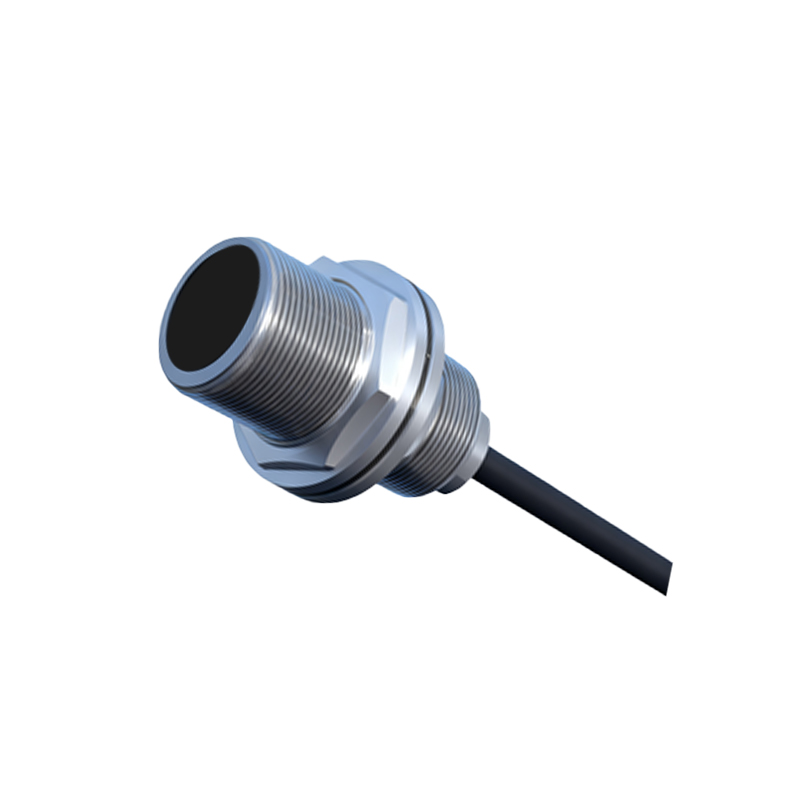
Decoding the Inductive Proximity Sensor Circuit
Inductive proximity sensors are predominantly used for detecting metallic objects. The heart of the circuit is an LC oscillator, where 'L' represents the sensor coil (the sensing face) and 'C' is a capacitor. The oscillator generates a high-frequency electromagnetic field. When a metallic object enters this field, eddy currents are induced on the object's surface. This causes a load on the oscillator, leading to a decrease in its oscillation amplitude. This change is detected by an amplitude detection circuit. The signal is then fed into a threshold trigger or comparator circuit. Once the amplitude drop exceeds a predefined threshold, the trigger circuit switches the state of the output driver. The output stage typically consists of a solid-state switch—either an NPN or PNP transistor—configured in a sinking or sourcing arrangement. The circuit diagram clearly shows the DC power supply connections (often 10-30V DC), the load (like a PLC input or relay), and the protective components such as reverse polarity protection diodes and surge suppression elements.
Analyzing Capacitive and Photoelectric Sensor Circuits
Capacitive sensor circuits share similarities with inductive ones but are designed to detect both metallic and non-metallic materials. The sensing element forms one plate of a capacitor, with the target object acting as the other plate. The circuit measures changes in capacitance. An oscillator's frequency shifts as the capacitance changes, which is then converted into a voltage change, processed, and used to trigger an output switch. These circuits often include sensitivity adjustment potentiometers. Photoelectric sensors, conversely, use light beams. The circuit diagram for a through-beam sensor shows separate emitter and receiver units. The emitter circuit drives an LED (often infrared) with a modulated current to avoid ambient light interference. The receiver circuit contains a phototransistor or photodiode, amplification stages, a demodulator to filter out the modulation frequency, and a comparator to produce a clean digital output. Reflective and diffuse mode sensors integrate both emitter and receiver into a single housing, with the circuit managing the emitted light and the reflected signal.
Output Configuration and Wiring Diagrams
A critical section of any proximity sensor datasheet is the wiring diagram. This illustrates the physical connections. The most common output types are 3-wire DC configurations: NPN (sinking) and PNP (sourcing). In an NPN circuit diagram, the output transistor connects the load to ground (0V). The load is wired between the positive supply and the sensor's output wire. When activated, the NPN transistor switches on, completing the circuit to ground and energizing the load. A PNP circuit does the opposite; the transistor connects the load to the positive supply. The load is wired between the output and ground. Two-wire AC/DC sensors are also prevalent, where the sensor and load are connected in series with the power supply, simplifying wiring but requiring careful consideration of leakage current. The diagrams always specify wire color codes (e.g., brown for +V, blue for 0V, black for output) and include symbols for protective devices like varistors for AC models.
Integration with Programmable Logic Controllers (PLCs)
In industrial control panels, proximity sensors are rarely standalone devices. Their circuit diagrams must be understood in the context of integration with a PLC. The sensor's output acts as a digital input to the PLC. For a 24V DC system using an NPN sensor, the PLC input module's common point is typically connected to 24V+. The sensor's output wire connects to the specific PLC input terminal. When the sensor detects an object, its NPN transistor conducts, pulling the PLC input point to near 0V, which the PLC registers as a logic '1' or 'ON' state. Conversely, a PNP sensor would connect to a sinking-type PLC input card. Misinterpreting the circuit diagram can lead to incorrect wiring, where