Understanding the 5-Wire Configuration
A 5-wire ultrasonic proximity sensor is a versatile device commonly used in industrial automation for precise non-contact distance measurement and object detection. Unlike simpler sensors, the five wires provide distinct functions for power supply, output signals, and configuration, allowing for greater flexibility and integration into complex control systems. Typically, these wires are color-coded for easy identification: brown for positive power supply, blue for negative power supply or ground, black for the normally open (NO) output, white for the normally closed (NC) output, and a fifth wire, often gray or another color, for an analog output or a complementary signal. Understanding this configuration is the critical first step before any physical connection is made. Always refer to the specific manufacturer's datasheet, as wire colors and functions can vary between models and brands.
Pre-Wiring Safety and Preparation
Before initiating the wiring process, ensure all safety protocols are followed. Disconnect power to the control circuit or panel where the sensor will be installed. Gather the necessary tools, including wire strippers, screwdrivers, and possibly a multimeter for verification. Examine the sensor's nameplate and documentation to confirm its voltage rating (commonly 10-30V DC) and output type (PNP or NPN sourcing). Prepare the cables: you will need a suitable power source matching the sensor's voltage, and the destination for the output signals, such as a programmable logic controller (PLC) input module, a relay, or another controller. Plan the cable routing to avoid interference from high-voltage power lines or sources of strong electromagnetic noise, which can affect the sensor's performance.
Connecting Power Supply Wires
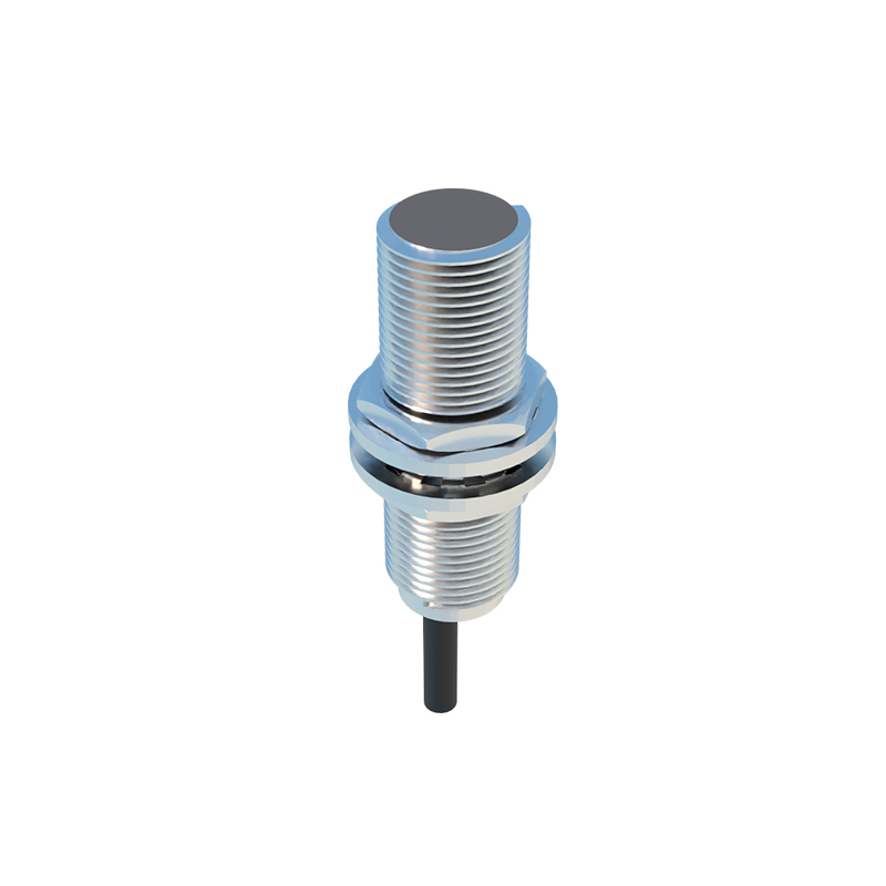
The foundation of the sensor's operation is a stable power supply. Locate the brown wire (typically V+ or positive) and the blue wire (typically 0V or negative/ground). Connect the brown wire to the positive terminal of your DC power supply. Connect the blue wire to the negative or ground terminal of the same power supply. It is imperative to observe correct polarity; reversing these connections can permanently damage the sensor. Use ferrules or properly terminated wire ends for a secure connection in the terminal block. Once these connections are secure and double-checked, you may apply power momentarily to verify basic functionality, such as a power indicator LED illuminating, if present.
Wiring the Digital Output Signals
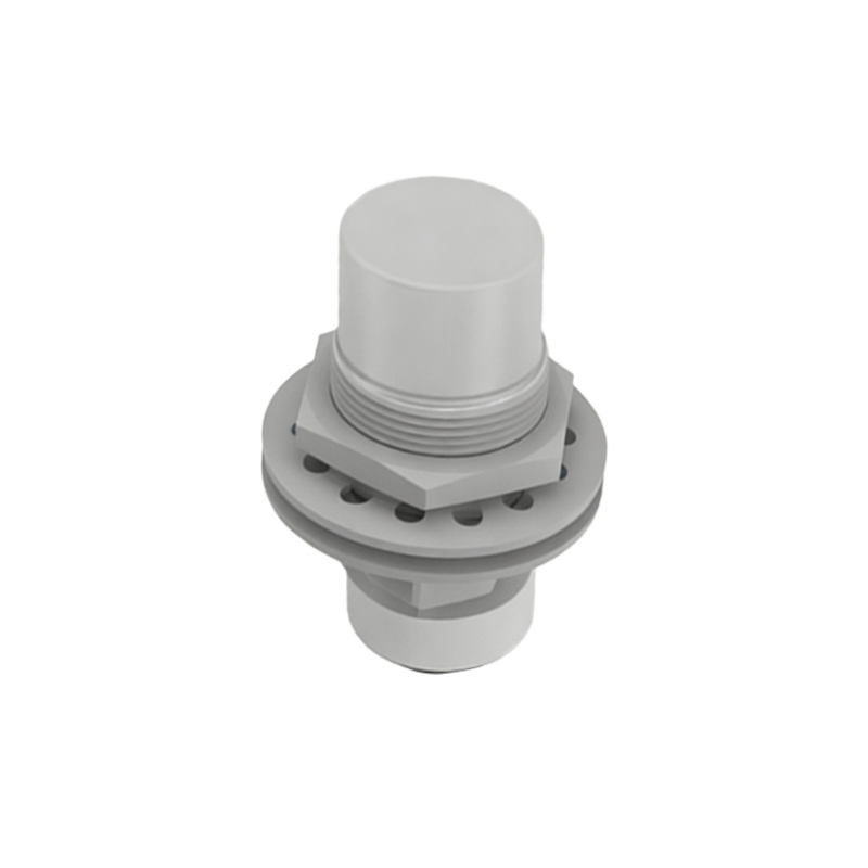
The digital outputs provide switch-like signals based on the detection state. The black wire usually represents the Normally Open (NO) output. In its default state (no target detected within the set range), this circuit is open. When a target is detected, it closes, completing the circuit to the connected device. The white wire typically represents the Normally Closed (NC) output, which operates inversely: it is closed in the default state and opens upon detection. Connect these wires to the appropriate input channels on your PLC, relay, or other control device. For a PNP-type sensor (sourcing), the black/white wires will supply voltage to the load when active; the load's other side should be connected to ground. Ensure the input device is compatible with the sensor's output current and voltage levels.
Integrating the Analog Output Wire
The fifth wire, often gray, is a key feature that enables continuous measurement. This wire provides an analog output signal, usually 0-10V or 4-20mA, proportional to the measured distance. This allows for precise positioning or level monitoring. Connect this wire to an analog input module on your PLC or controller. For a voltage output, ensure the input impedance is high enough to avoid loading the signal. For a current output, the input must be configured as a current sink. You must also configure the scaling parameters within your controller's software to translate the analog signal (e.g., 4mA = 0 mm, 20mA = 1000 mm) into meaningful engineering units. This wire may share the common blue ground wire or require a separate reference, so consult the datasheet.
Configuration and Testing Procedures
After all physical connections are complete, configuration is necessary. Many 5-wire sensors have teach-in buttons or potentiometers to set the switching points (for digital outputs) and the analog output range. Use a small screwdriver to adjust the sensing range and hysteresis as needed. For testing, apply power and use a target object at a known distance. Observe the digital output LEDs on the sensor (if available) and verify the state changes on your PLC's input indicators. Use a multimeter to measure the analog output voltage or current at different distances to