Introduction to Metal Proximity Sensors
Metal proximity sensors are essential components in industrial automation, widely used for detecting the presence or absence of metallic objects without physical contact. These sensors operate based on electromagnetic principles, offering high reliability and durability in harsh environments. They are commonly found in manufacturing lines, robotics, and safety systems, where precise detection is critical for operational efficiency. The ability to sense metals through non-contact means reduces wear and tear, minimizing maintenance needs and enhancing system longevity. This article provides a comprehensive, diagram-based explanation of their working mechanisms, tailored for engineers and technicians in the electrical and automation fields.
Core Operating Principle: Electromagnetic Induction
At the heart of metal proximity sensors lies electromagnetic induction, a phenomenon where a changing magnetic field generates an electrical current in a conductor. The sensor contains an oscillator circuit that produces a high-frequency electromagnetic field around its sensing face. When a metallic object enters this field, eddy currents are induced on the object's surface due to the alternating magnetic flux. These eddy currents create their own magnetic field, which opposes the original field from the sensor. This opposition results in a change in the oscillator's amplitude or frequency, triggering the sensor's output switch. The process is highly efficient for detecting ferrous metals like iron and steel, which have strong magnetic properties, but it also works for non-ferrous metals such as aluminum or copper, albeit with reduced sensing ranges.
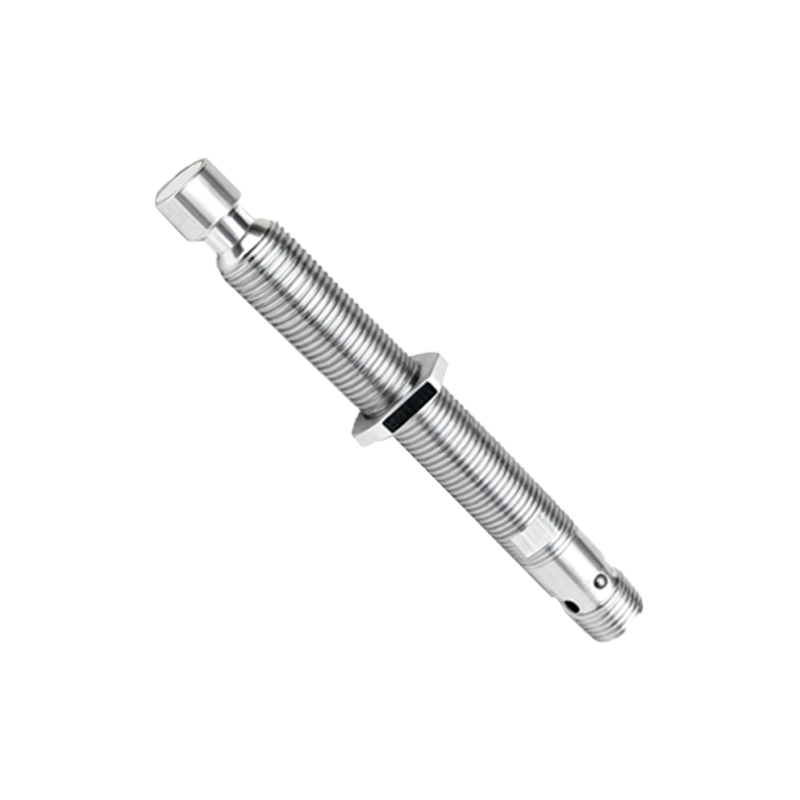
Internal Components and Circuit Diagram
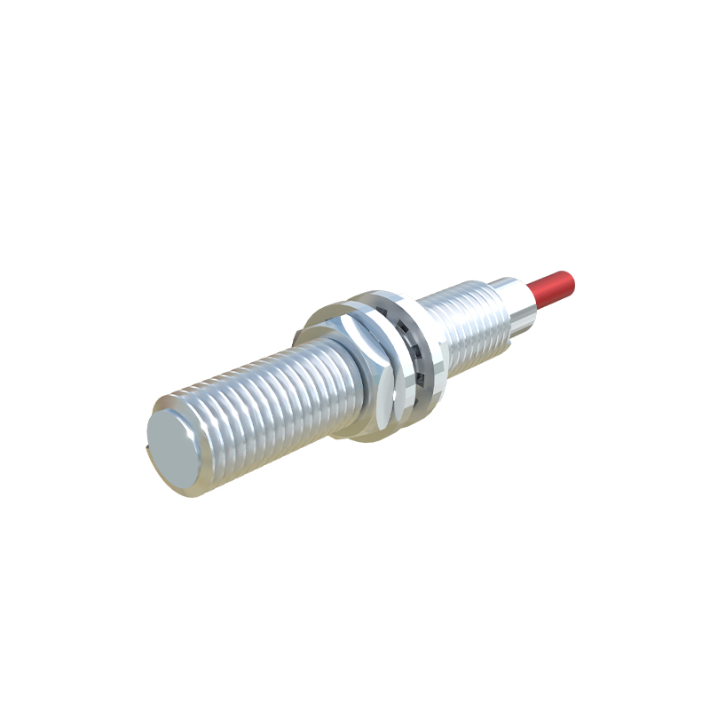
A typical metal proximity sensor comprises several key parts: an oscillator coil, a demodulator, an amplifier, and an output stage. The oscillator generates the high-frequency field, while the demodulator converts the changes in oscillation into a detectable signal. This signal is then amplified to drive the output, which can be a transistor (for DC sensors) or a triac (for AC sensors), providing a switching action. In a circuit diagram, the oscillator is connected to a resonant LC circuit, with the coil acting as the inductive component. When a metal object interferes, the LC circuit's impedance shifts, altering the oscillation. The demodulator rectifies this change, and the amplifier boosts it to activate the output. Diagrams often illustrate these stages with labeled blocks, showing how energy flows from the power supply through the oscillator to the output, highlighting the sensor's response to metal proximity.
Types of Metal Proximity Sensors
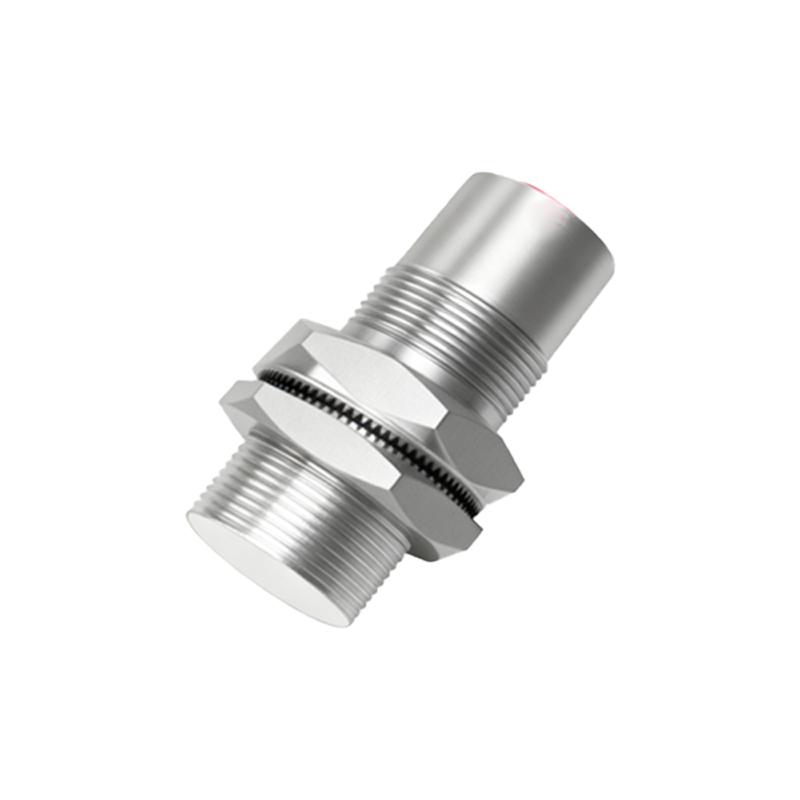
Metal proximity sensors are categorized based on their detection methods and output configurations. Inductive proximity sensors are the most common, using electromagnetic induction as described. Within this category, shielded (flush-mountable) sensors have a limited lateral detection range, making them ideal for embedded installations, while unshielded (non-flush) sensors offer a wider range but require more space. Another type is the capacitive proximity sensor, which can detect both metals and non-metals by measuring changes in capacitance, though it's less specific for metal-only applications. Additionally, sensors vary by output type: NPN (sinking) and PNP (sourcing) for DC versions, and NO (normally open) or NC (normally closed) contacts. Selection depends on factors like the target metal, sensing distance, environmental conditions, and compatibility with control systems.
Step-by-Step Working Process with Diagrams
To visualize the operation, consider a diagram showing a metal proximity sensor in a typical setup. Step 1: The sensor is powered on, and the oscillator generates a stable electromagnetic field around its active surface. Step 2: A metal object approaches within the specified sensing range, entering the field. Step 3: Eddy currents form on the metal surface, creating an opposing magnetic field that dampens the oscillator's energy. Step 4: The demodulator detects this damping as a voltage drop or frequency shift. Step 5: The amplifier processes the signal, and if it exceeds a threshold, the output switches state—for example, from OFF to ON. Step 6: This change sends a signal to a connected device, like a PLC or relay, initiating an action such as stopping a conveyor. Diagrams often use arrows to indicate field lines and current flow, with annotations explaining each stage for clarity.
Factors Affecting Performance and Accuracy
Several factors influence the effectiveness of metal proximity sensors. Sensing distance is critical and varies with metal type; ferrous metals allow longer ranges than non-ferrous ones. Environmental conditions like temperature extremes, humidity, or exposure to chemicals can affect the sensor's materials and electronics, potentially reducing lifespan. Electrical noise from nearby motors or cables may interfere with the oscillator, causing false triggers, so proper shielding and installation are essential. Target size and shape also matter—larger, flat surfaces are easier to detect than small or