Fundamentals of Electromagnetic Induction
Electromagnetic induction proximity sensors operate on the foundational principle discovered by Michael Faraday. When an electrically conductive target enters the alternating magnetic field generated by the sensor's oscillator coil, eddy currents are induced on the target's surface. These eddy currents create their own opposing magnetic field, which interacts with the sensor's original field. This interaction results in a measurable change in the oscillator's amplitude or frequency. The sensor's detection circuit is precisely tuned to monitor this change. Once the disturbance reaches a predetermined threshold, the sensor's output state switches, signaling the presence of the target. This non-contact detection method is highly reliable for metallic objects, offering immunity to surface conditions like dust, oil, or moisture that often plague mechanical switches.
Core Components and Internal Architecture
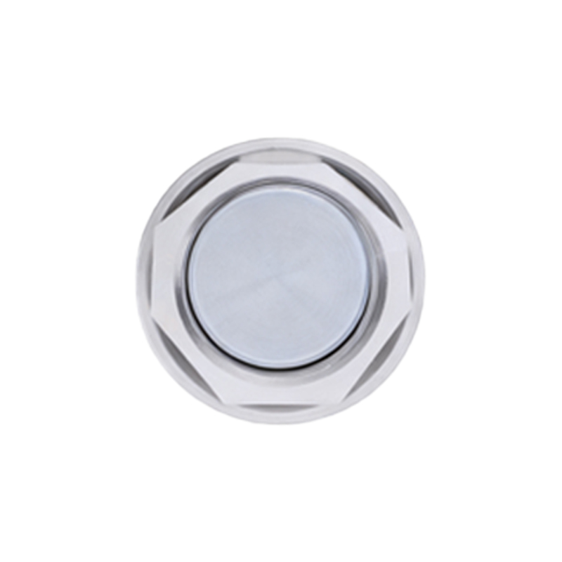
The internal architecture of a standard inductive proximity sensor is elegantly engineered for robustness. At its heart lies the oscillator circuit, which generates the high-frequency electromagnetic field. This is coupled with a detection coil, often wound around a ferrite core to focus the field. The signal from the coil is fed into a trigger circuit, which analyzes the amplitude damping. A solid-state output stage, typically featuring a transistor (PNP or NPN), provides the switching signal. Modern sensors integrate sophisticated ASICs (Application-Specific Integrated Circuits) that manage oscillation, detection, and output functions with high precision. The entire assembly is encapsulated in a housing made of materials like nickel-plated brass, stainless steel, or PBT plastic, ensuring protection against mechanical shock, vibration, and harsh industrial fluids.
Key Performance Characteristics and Specifications
Understanding sensor specifications is critical for proper application. The rated sensing distance (Sn) is the nominal range for a standard target, usually a square of mild steel. Factors like target material, size, and shape significantly influence the actual sensing distance; for instance, copper or aluminum reduces the effective range. Repeat accuracy defines the sensor's consistency in detecting a target at the same point. Switching frequency indicates how many on/off cycles per second the sensor can handle, crucial for high-speed counting applications. Hysteresis, a built-in differential between the switch-on and switch-off points, prevents output chattering when a target is at the edge of the sensing range. Other vital specs include voltage range, current consumption, output type (NO/NC), and protection ratings like IP67 or IP69K for environmental sealing.
Common Industrial Applications and Use Cases
Inductive proximity sensors are ubiquitous in automation. A primary application is position sensing, such as verifying the presence of a metal part on a conveyor, detecting the end-of-travel of a cylinder, or confirming the closure of a safety guard. They are indispensable in counting and sorting systems, where they tally metal objects passing by at high speeds. In machine tools, they provide precise feedback for tool positioning and turret indexing. Vibration-resistant models monitor rotational speed and detect overspeed conditions in motors and gearboxes. Their sealed variants are extensively used in food and beverage, automotive wash tunnels, and pharmaceutical packaging lines where exposure to caustic cleaners and high-pressure sprays is routine.
Selection Criteria for Optimal Performance
Selecting the right sensor requires a systematic approach. First, identify the target material; ferrous metals offer the longest range, while non-ferrous metals require sensors with a reduced factor. Determine the required sensing distance and choose a sensor with a rated distance 10-20% greater to account for installation tolerances and temperature drift. The housing style—barrel (threaded), rectangular, or ring-shaped—must suit the mounting constraints. Environmental conditions dictate the necessary ingress protection (IP) rating and material compatibility. Electrical characteristics are paramount: ensure the supply voltage (DC or AC) matches, and select the correct output configuration (sourcing PNP or sinking NPN) to interface with the PLC or controller. For high-speed applications, verify the switching frequency meets or exceeds the required pulse rate.
Installation Best Practices and Troubleshooting
Proper installation maximizes sensor lifespan and reliability. Maintain the recommended clearance from surrounding metal structures, known as the flush-mounting or non-flush-mounting distance, to prevent false triggering. Secure mounting is essential to withstand vibration. For wired connections, use shielded cables in electrically noisy environments and ground the shield at the controller end only. Common issues include failure to detect, which may stem from an incorrect target material, insufficient sensing distance, or a misaligned target. Constant output activation can be caused by sensor damage, metallic debris in the sensing field, or a faulty load. Always refer to the manufacturer's datasheet for specific installation diagrams, wiring schematics, and diagnostic LED indicators to streamline troubleshooting.