Introduction to 3-Wire Proximity Sensors
Proximity sensors are indispensable components in modern industrial automation, providing non-contact detection of metallic or other objects. Among the various configurations, the 3-wire proximity sensor stands as the most prevalent and versatile type used in countless applications. Unlike their 2-wire counterparts, which are simpler but have limitations in switching capacity and voltage drop, 3-wire sensors offer superior performance, reliability, and easier integration into control systems. They are the workhorses of assembly lines, packaging machinery, robotic cells, and material handling systems, where precise and repeatable detection is critical for operational efficiency and safety. This guide delves into the operational principles, wiring configurations, key specifications, and practical considerations for effectively deploying these sensors.
Core Operating Principle and Sensing Technologies
At its heart, a 3-wire proximity sensor operates by generating an electromagnetic field from its sensing face. When a target object enters this field, it causes a change in the oscillation amplitude or other electrical characteristics within the sensor's internal oscillator circuit. This change is detected and processed by the sensor's circuitry, which then triggers a solid-state switching output. The "3-wire" designation refers to the three essential connections: a positive supply voltage (typically brown wire), a negative or ground (blue wire), and a switched output signal (black wire). The primary sensing technologies include Inductive sensors, designed to detect ferrous and non-ferrous metals, and Capacitive sensors, capable of detecting a wider range of materials including plastics, liquids, and powders. The choice depends entirely on the application's target material.
Wiring Configurations: NPN vs. PNP Sourcing
A fundamental aspect of 3-wire sensors is the output transistor type, which defines the wiring and logic. This creates two main categories: NPN (Sinking) and PNP (Sourcing) outputs. In a PNP sensor, the output wire switches the positive voltage. When active, the output terminal connects to the positive supply, sourcing current to the load (e.g., a PLC input). This configuration is often the standard in many regions, including Europe. Conversely, an NPN sensor switches the negative or ground path. When active, it connects the load to ground, sinking current from it. NPN wiring is common in some Asian markets. Understanding this distinction is crucial for proper interface with Programmable Logic Controllers (PLCs) and other control devices. Incorrect matching can lead to system malfunctions or damage.
Key Electrical Specifications and Performance Parameters
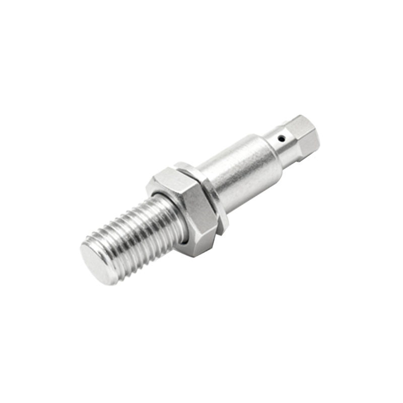
Selecting the right sensor requires careful analysis of its specifications. The operating voltage range, often 10-30V DC, must be compatible with the plant's control voltage. The output current rating must not be exceeded to avoid damaging the internal switch. Sensing distance, or nominal range (Sn), is specified for a standard target; real-world sensing distance can be less and is affected by target material, size, and shape. Response frequency indicates how quickly the sensor can detect objects passing by, a vital parameter for high-speed applications. Other critical specs include housing material (metal or plastic for different environments), IP rating for ingress protection against dust and water, and temperature range. Short-circuit and reverse polarity protection are also highly desirable features for robustness.
Practical Installation and Troubleshooting Tips
Correct installation ensures optimal performance and longevity. Sensors must be mounted securely to prevent vibration-induced failure or misalignment. Maintaining the proper gap between the sensor face and the target is essential; mounting too close can cause physical damage, while excessive distance leads to unreliable detection. It is also critical to consider the sensing field's shape and potential interference from surrounding metal structures, other sensors, or electrical noise. For troubleshooting, a systematic approach is best: verify power supply voltage and polarity, check for the correct target within the sensing range, inspect wiring connections for integrity, and use the sensor's indicator LED (if present) to confirm switching status. Understanding whether the output is normally open (NO) or normally closed (NC) is also essential for diagnosing logic issues.
Advantages Over 2-Wire and 4-Wire Alternatives
The 3-wire design strikes an optimal balance between performance and complexity. Compared to 2-wire sensors, which are wired in series with the load, 3-wire sensors have a dedicated output line. This eliminates the residual voltage drop or leakage current associated with 2-wire models, ensuring a crisp, full-voltage signal to the PLC and allowing for higher switching currents. They also offer more reliable operation with low-power loads. Compared to more complex 4-wire sensors, which often provide both a normally open and a normally