Understanding Proximity Sensor Response Time Fundamentals
Proximity sensor response time, often referred to as switching frequency or response frequency, is a critical performance parameter defined as the maximum number of on/off cycles a sensor can complete per second. A slow response manifests as a delay between the target entering the sensing range and the output signal change. This lag can cause missed counts, improper sequencing, and reduced machine efficiency. The specified response time in datasheets is typically measured under ideal laboratory conditions. In real-world industrial applications, numerous factors can degrade this performance, leading to operational bottlenecks. Understanding that response time is influenced by an interconnected system—sensor, target, environment, and circuitry—is the first step toward effective troubleshooting.
Primary Causes of Delayed Sensor Response
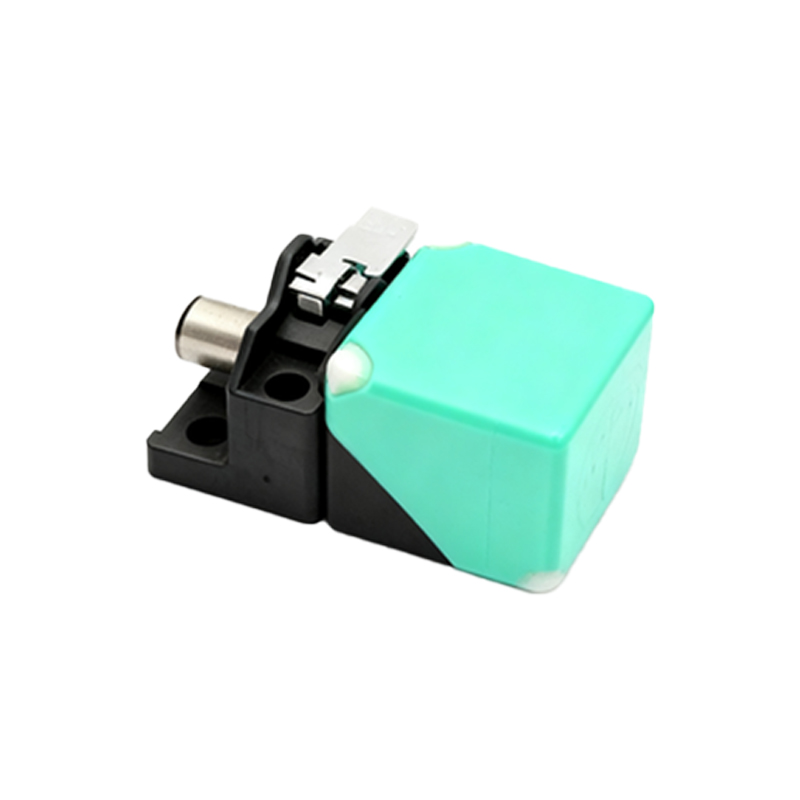
Several key factors contribute to sluggish proximity sensor performance. Electrical noise interference from nearby motors, variable frequency drives (VFDs), or welding equipment is a predominant cause. This noise can induce false signals or require the sensor's internal circuitry to filter, thereby slowing down its reaction. Inadequate power supply quality, including voltage drops, ripple, or instability, directly impacts the sensor's switching speed. The physical characteristics of the target are equally crucial; a target smaller than the sensor's rated standard, or composed of a material with lower conductivity or magnetic permeability (for inductive sensors), will increase the required sensing distance and slow the response. Sensor wear, internal component aging, and accumulated contamination like metal dust or oil film on the sensing face also degrade performance over time.
Systematic Troubleshooting and Diagnostic Procedures
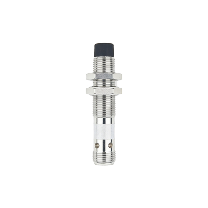
Begin diagnostics with a visual and physical inspection. Check the sensor face for buildup and clean it with a soft cloth and appropriate solvent. Verify the target's size, material, and approach angle align with the sensor's specifications. Use a reliable multimeter or an oscilloscope to measure the supply voltage at the sensor's terminals during operation to rule out drops. Monitor the output signal with an oscilloscope to visualize the actual response delay and check for noise on the signal line. Temporarily bypass long cable runs with a short test cable to identify issues related to cable capacitance or damage. Isolate the sensor from potential noise sources by powering it temporarily with a separate, clean power supply. Documenting baseline performance when the system is new provides invaluable data for comparison during troubleshooting.
Optimizing Installation and Electrical Configuration
Proper installation is paramount for optimal speed. Ensure the target approaches the sensor head perpendicularly and within the specified operating distance, typically 70-80% of the rated sensing distance. For high-speed applications, use sensors specifically designed with fast-response circuitry, often labeled "High-Speed" or with very high switching frequencies (e.g., 5 kHz or above). Electrically, implement robust noise suppression strategies: use shielded cables, ground the shield properly at the controller end only, and install ferrite cores near the sensor. For DC sensors, ensure a stable, regulated power supply. In noisy environments, consider using sensors with built-in diagnostics or short-circuit protection that doesn't excessively compromise speed. Keep sensor wiring separate from high-voltage AC power lines and motor leads.
Selecting the Right Sensor for High-Speed Applications
When new sensor selection is necessary, prioritize models with inherently fast response times. Compare datasheet values for switching frequency. For inductive sensors detecting small metals, factor-frequency or analog-output models can offer speed advantages in certain setups. Capacitive sensors for non-metals generally have slower response; ensure the chosen model meets the minimum speed requirement. For the ultimate in speed, consider specialized sensors like cylindrical "factor 1" inductive models or rectangular designs optimized for fast switching. Don't overlook the output type: PNP (sourcing) vs. NPN (sinking) performance is identical, but the connected controller's input card characteristics can affect perceived speed. Always consult with the sensor manufacturer's application engineers for demanding high-cycle applications.
Advanced Solutions and Preventative Maintenance
For persistent issues, advanced solutions may be required. Implement signal conditioners or fast-response PLC input modules designed to handle brief pulses. Review and optimize the machine's control logic; sometimes, software filters or delays in the PLC program can inadvertently slow the system. A comprehensive preventative maintenance (PM) schedule is the best defense. Regularly clean sensors, check mounting integrity, and verify electrical connections. Periodically test response time with a calibrated oscilloscope or a high-speed timer counter as part of the PM routine. Keeping a log of sensor performance and environmental conditions helps predict failures before they cause unplanned downtime, ensuring sustained high-speed operation.