Introduction to Hall Effect Proximity Switches in CAD
The integration of Hall Effect proximity switches into modern industrial control systems necessitates precise planning and documentation, a task where Computer-Aided Design (CAD) becomes indispensable. A CAD drawing for a Hall Effect sensor is far more than a simple illustration; it is a detailed technical document that communicates critical information about the device's physical dimensions, mounting requirements, electrical connections, and operational environment. These drawings serve as the universal language between design engineers, panel builders, installation technicians, and maintenance personnel. For an electrical engineer, the ability to accurately interpret and create these drawings is fundamental to ensuring system reliability, safety, and functionality. The drawing encapsulates the electromechanical interface of the sensor, translating its datasheet specifications into a spatial and contextual blueprint for integration.
Key Components of a Hall Effect Sensor CAD Drawing
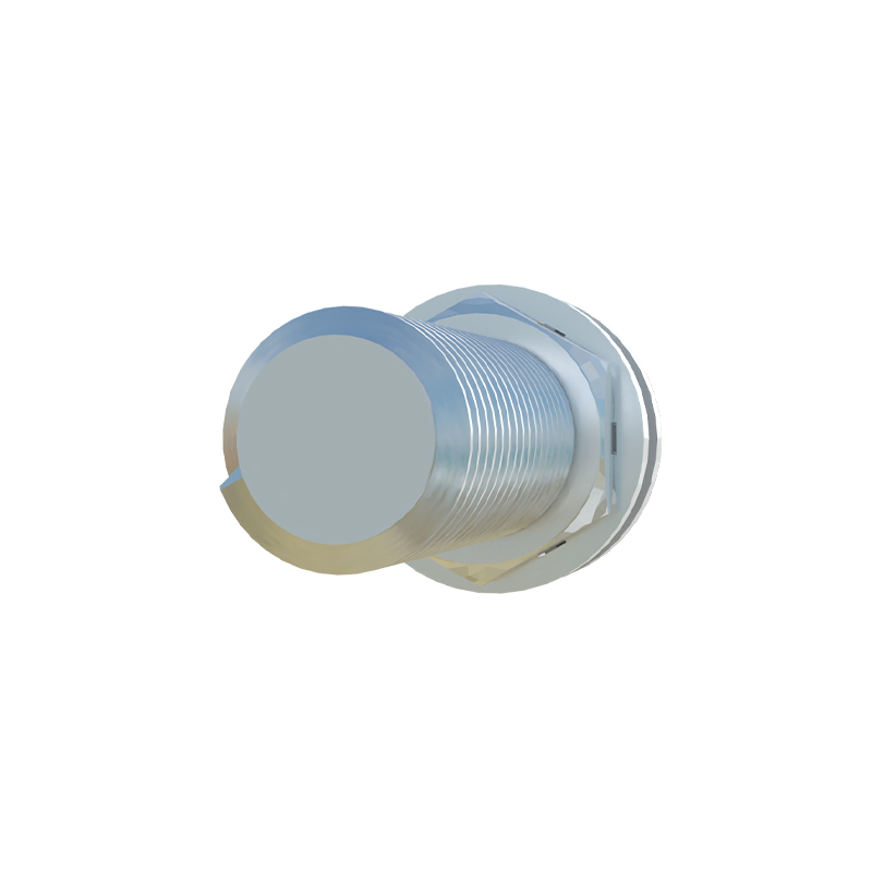
A standard CAD drawing for a Hall Effect proximity switch typically comprises several views and data blocks. The primary orthographic views—front, side, and top—provide exact outer dimensions, including the sensor body's length, width, and height, as well as the thread size for cylindrical models. A detailed section view is often included to show internal components like the Hall IC, magnet, and terminal block, which is crucial for understanding sensing range and potential interference. The connection diagram, usually presented as a schematic view or within a table, specifies pin assignments (e.g., Vcc, Output, GND), output types (PNP/NPN, NO/NC), and wire colors. Furthermore, the drawing includes a mounting dimension diagram, illustrating clearances required for proper operation and the precise location of the sensing face relative to mounting holes.
Symbolic Representation and Schematic Integration
In electrical schematic diagrams within a CAD environment like AutoCAD Electrical or EPLAN, the Hall Effect sensor is represented by a standardized symbol. This symbol abstracts the physical device into its logical electrical function. It typically consists of a square or rectangle representing the sensor element, with connection points for power supply, ground, and the output signal. A small diamond shape or a special notation often indicates the switching element. The accompanying tag or component designation links this symbol to the detailed part number and the mechanical CAD drawing in the bill of materials (BOM). Accurate schematic representation is vital for generating correct wiring lists, terminal plans, and for performing electrical rule checks to prevent design errors in the control circuit.
Critical Dimensions and Tolerances for Installation
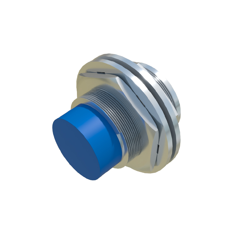
One of the most scrutinized sections of the CAD drawing is the dimensioning block. For Hall Effect sensors, specific dimensions are paramount. The "sensing distance" (Sn) must be clearly noted, often with a graphical indicator showing the effective range from the active face. Mounting hole patterns, thread depths, and wrench flats (for barrel sensors) are dimensioned with geometric tolerances. The drawing must also specify the "repeat accuracy" and "hysteresis" zones graphically or numerically. Engineers must pay close attention to the "flush-mountable" or "non-flush" designation, as this dramatically affects the required lateral and frontal clearance from metal surfaces, which is always detailed in the installation diagrams to prevent shielding or false triggering.
Material Specifications and Environmental Ratings
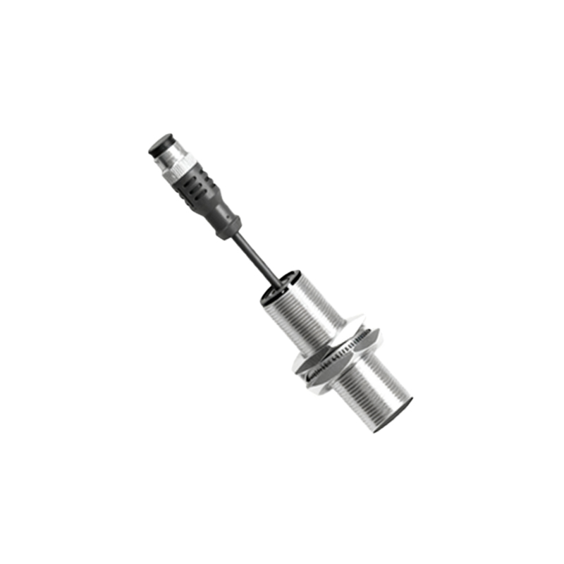
The material callouts and finish specifications on the CAD drawing directly impact the sensor's durability and application suitability. The housing material, typically nickel-plated brass, stainless steel, or PBT plastic, will be specified. The IP (Ingress Protection) rating, such as IP67 or IP69K, is prominently displayed, indicating the level of protection against dust and water. The operating temperature range, shock and vibration resistance ratings, and compliance with standards like UL, CE, or IEC are also listed in the title block or a notes section. These details ensure the selected sensor will survive the environmental conditions of its intended application, whether in a cleanroom or on a heavy-duty machining center.
Output Configuration and Electrical Interface Details
The electrical characteristics are precisely defined. The drawing will specify the supply voltage range (e.g., 10-30V DC), current consumption, and the maximum load current for the output. For the output stage, the configuration—be it PNP normally open (NO), NPN normally closed (NC), or analog (0-10V/4-20mA)—is unambiguously stated. Wiring diagrams show the connection to the load (e.g., a PLC input module or a relay coil), including the necessity for a pull-up/pull-down resistor or a protection diode for inductive loads. This section eliminates ambiguity during panel wiring and commissioning, preventing potential damage to the sensor or the controller.