Introduction to Capacitive Proximity Sensing
A capacitive proximity sensor is a non-contact device that detects the presence or absence of an object, or measures its distance, based on the principle of capacitance. Unlike inductive sensors that detect only metals, capacitive sensors can detect a wide range of materials including plastics, glass, liquids, and granular substances. The core principle involves changes in an electrical field. The sensor forms one plate of a capacitor, with the target object acting as the other plate. As the object enters the sensing field, it alters the dielectric constant and thus the capacitance of the system. This change is then converted into a usable electrical signal, typically a switching output.
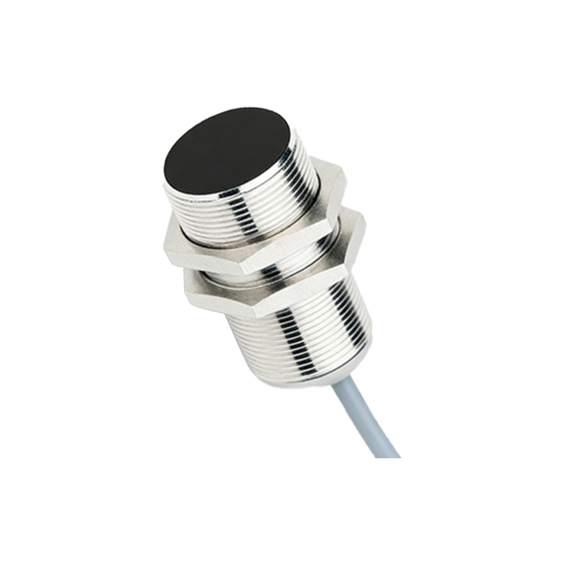
Fundamental Circuit Components and Architecture
The basic architecture of a capacitive proximity sensor circuit comprises several key components. At its heart is an oscillator circuit, often a high-frequency RC or LC oscillator, which generates an alternating electric field from the sensor's active surface or electrode. This electrode is connected to the oscillator's feedback network. A demodulator or detector circuit follows, responsible for converting the high-frequency AC signal into a DC voltage level proportional to the amplitude. This DC signal is then fed into a comparator or Schmitt trigger circuit. The comparator compares the signal against a predefined reference voltage (the sensitivity threshold). When the signal exceeds this threshold, the output stage—usually a solid-state switch like an NPN/PNP transistor or an open-collector configuration—activates.
Detailed Circuit Diagram Analysis
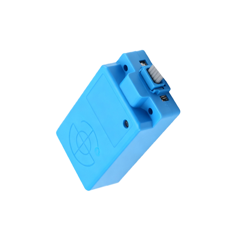
A typical circuit diagram begins with the sensing electrode, which can be a simple metal plate. This electrode is connected to the feedback path of an oscillator, such as a Colpitts or a capacitive feedback oscillator. Resistors and a small capacitor in the feedback loop set the base frequency, often in the range of 100 kHz to 1 MHz. The oscillating signal is capacitively coupled to a peak detector circuit using a diode and a capacitor. The resulting DC voltage is smoothed by a filter capacitor. This voltage is applied to the non-inverting input of an operational amplifier configured as a comparator. A potentiometer connected to the voltage divider network provides the adjustable reference voltage to the inverting input, allowing for sensitivity calibration. The comparator's output drives the base of an NPN transistor through a current-limiting resistor. The transistor's collector is connected to the output terminal and a pull-up resistor, providing a clean switched signal.
The Role of Oscillator Design and Frequency
Oscillator stability is paramount for reliable sensing. The circuit is designed so that the presence of a target object increases the system's capacitance (C). In an RC oscillator, frequency (f) is inversely proportional to RC (f ≈ 1/(2πRC)). An increase in C causes a decrease in oscillation frequency. However, many practical circuits are amplitude-based. Here, the increased capacitance loads the oscillator, dampening the oscillation amplitude rather than drastically shifting the frequency. This amplitude reduction is the primary detected parameter. Shielding techniques and guard rings around the active electrode are often incorporated into the PCB layout to minimize stray capacitance and direct the electric field forward, enhancing stability and directivity.
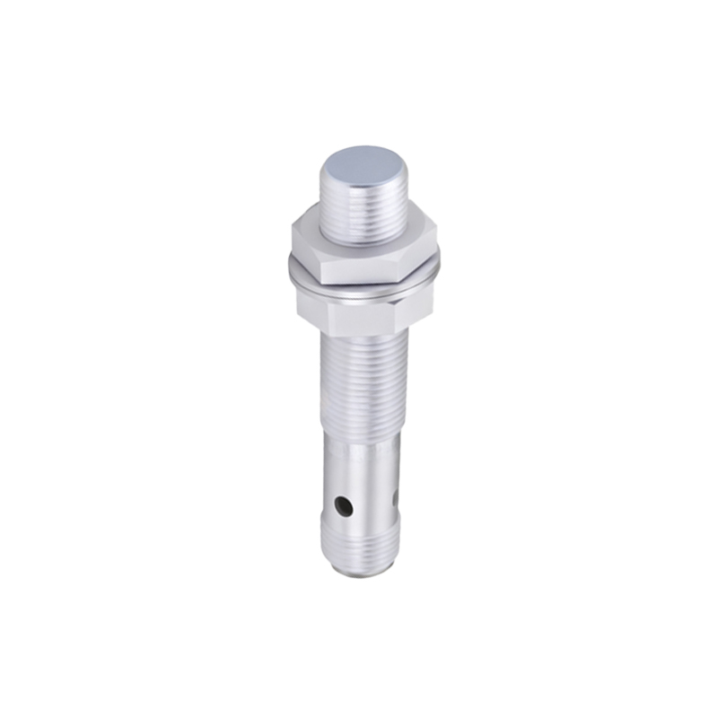
Sensitivity Adjustment and Calibration Circuitry
Precise sensitivity control is achieved through the reference voltage circuit. A voltage divider, with one resistor being a multi-turn potentiometer, creates a variable threshold. Engineers can calibrate the sensor for specific materials and distances by adjusting this potentiometer. Some advanced circuits include a hysteresis network around the comparator, using positive feedback from the output to the non-inverting input. This creates two threshold levels: one for turn-on and a lower one for turn-off. Hysteresis prevents output chattering when the sensed signal is near the threshold, ensuring a clean, bounce-free switch even in noisy industrial environments.
Output Stage Configurations and Load Considerations
The final stage interfaces the sensor with control systems like PLCs or relays. Common configurations include NPN (sinking) and PNP (sourcing) transistor outputs. In an NPN configuration, the load is connected between the output terminal and the positive supply voltage (V+). When the sensor activates, the NPN transistor saturates, connecting the output to ground (0V), thus "sinking" current. The PNP configuration does the opposite, "sourcing" current to the load when active. Many sensors also feature analog outputs (0-10V or 4-20mA) for distance measurement, requiring an additional voltage-to-current converter circuit. Protection components like flyback diodes for inductive loads and series resistors for current limiting are critical for longevity.
Practical Design Considerations and Noise Immunity
Designing a robust capacitive sensor requires addressing real-world challenges.