Introduction to Proximity Sensing Technology
Proximity sensors are fundamental components in modern industrial automation, enabling the detection of objects without physical contact. These devices operate on various principles, including inductive, capacitive, ultrasonic, and photoelectric methods. The internal structure of a proximity sensor is meticulously engineered to translate a physical phenomenon into a reliable electrical signal. This intricate design ensures high precision, durability, and immunity to environmental factors like dust, oil, and vibration. Understanding the internal architecture is crucial for engineers to select the appropriate sensor for specific applications, ranging from assembly line positioning to safety interlocks. The core of any proximity sensor is its sensing element, oscillator circuit, signal conditioner, and output stage, all housed within a robust casing.
Core Sensing Element and Principle of Operation
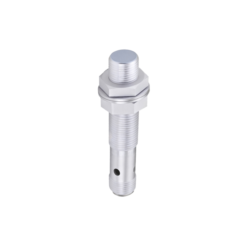
The heart of a proximity sensor is its sensing element, which varies by type. In an inductive proximity sensor, this is a coil wound around a ferrite core, connected to a high-frequency oscillator. When a metallic object enters the sensor's electromagnetic field, eddy currents are induced in the target. This causes a change in the oscillation amplitude, which is detected by a threshold circuit. Capacitive sensors, designed for non-metallic materials, use a capacitor formed by the sensor face and the target as one plate and an internal electrode as the other. Changes in capacitance due to the target's presence alter the oscillator's frequency. Photoelectric sensors employ an LED or laser diode as an emitter and a phototransistor or photodiode as a receiver, detecting changes in light intensity or time-of-flight.
The Oscillator and Signal Conditioning Circuitry
Surrounding the sensing element is the oscillator circuit, typically generating frequencies in the range of 100 kHz to 1 MHz for inductive types. This circuit creates the alternating electromagnetic field. The key internal component here is the stability of the oscillator; it must be insensitive to temperature fluctuations and supply voltage variations. Following the oscillator is the signal conditioning stage. This includes a demodulator to convert the high-frequency AC signal into a DC level and an amplifier to boost the weak signal. A critical sub-circuit is the Schmitt trigger or comparator, which compares the conditioned signal to a predefined threshold. This component is responsible for providing a clean, hysteresis-enabled digital switch signal, preventing output chatter when the target is at the detection boundary.
Output Stage and Switching Mechanisms
The output stage converts the processed detection signal into a usable control signal. Common configurations include NPN (sinking), PNP (sourcing), analog (4-20 mA or 0-10V), and push-pull outputs. Internally, this stage consists of a power transistor, typically a MOSFET or a bipolar junction transistor, which acts as the electronic switch. For solid-state outputs, protection elements like flyback diodes for inductive loads, current-limiting resistors, and transient voltage suppressors are integrated onto the circuit board to safeguard against voltage spikes and short circuits. Some advanced models incorporate short-circuit and overload protection directly into the IC logic, enhancing reliability. The output stage is physically and electrically isolated from the sensing circuitry to minimize noise interference.
Housing, Encapsulation, and Environmental Sealing
The internal electronics are protected by a durable housing, usually made of nickel-plated brass, stainless steel, or engineered plastics like PBT. A critical internal feature is the potting compound—an epoxy or silicone resin that fully encapsulates the circuit board and coil assembly. This potting provides exceptional mechanical stability, vibration resistance, and thermal conductivity to dissipate heat. It also acts as a barrier against moisture, corrosive chemicals, and dust ingress, often enabling ingress protection ratings of IP67 or higher. The sensor face, especially in inductive models, is made of a specific material (like PTFE or a specialized ceramic) that allows the electromagnetic field to pass through while protecting the coil from physical damage.
Specialized Features and Advanced Internal Designs
Modern proximity sensors integrate sophisticated features that add complexity to their internal structure. Temperature compensation circuits use thermistors or integrated logic to adjust sensitivity across an operating range. Embedded microcontrollers allow for programmability, enabling adjustable sensing ranges, output delays (on/off delay), and diagnostic functions like IO-Link communication. In noise-prone environments, internal shielding and filtering circuits are paramount. The coil and critical signal paths are often shielded with mu-metal or carefully designed ground planes on the PCB to reject electromagnetic interference from motors or frequency drives. This internal EMI/RFI shielding is a key differentiator for sensors used in heavy industrial settings.
Conclusion: The Synergy of Internal Components
The performance of a proximity sensor is a direct result of the precise integration and synergy of its internal components. From the generation of the sensing field to the